Introduction
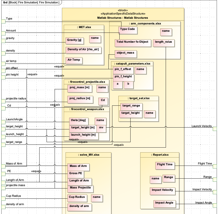
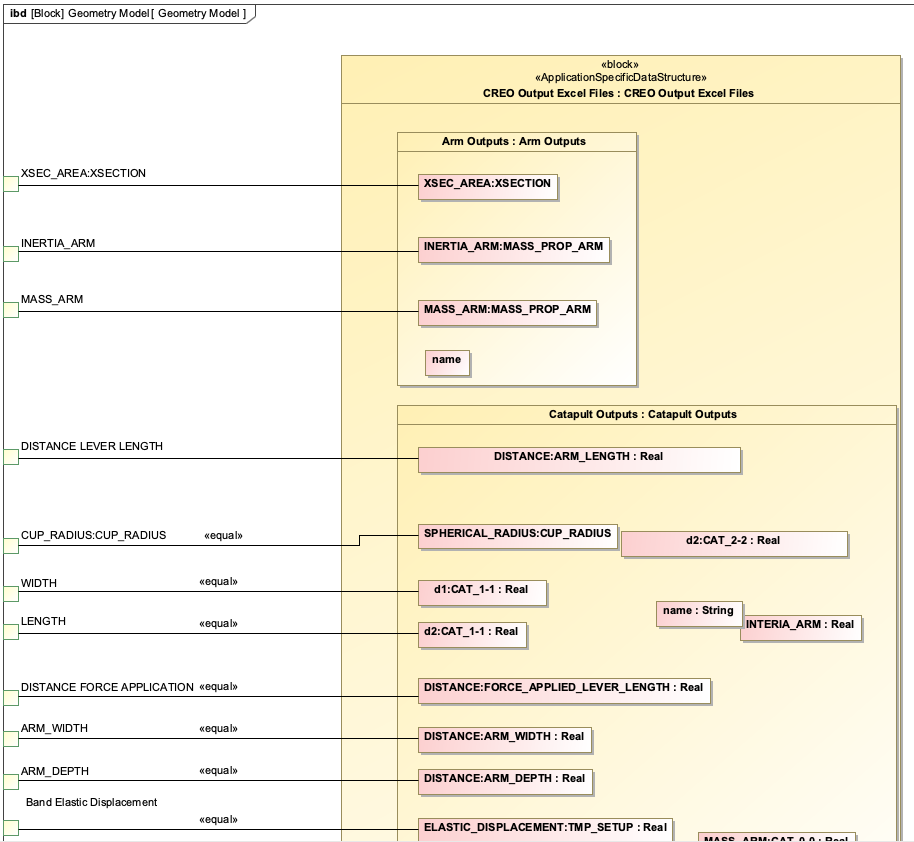
An Internal Block Diagram (IBD) is a SysML diagram that shows how a system is composed of parts, how those parts connect through interfaces, and the flows (like force, electricity, or data) that move between those interfaces.
Overview
Internal Block Diagrams (IBDs) are a core SysML diagram type used to represent the internal structure and connections within a system. They provide a detailed view of how components interact, making them essential for model-based systems engineering (MBSE) and digital engineering (DE) workflows.
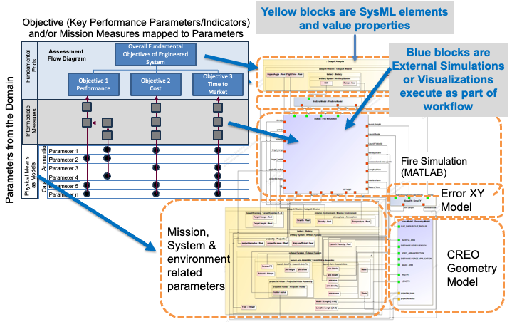
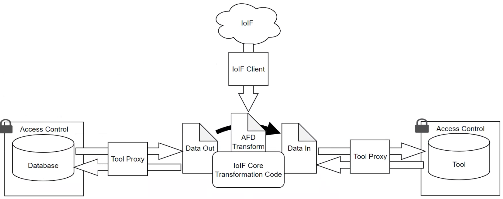
IBDs are particularly valuable in the context of IoIF (Armaments Interoperability and Integration Framework) because they: - Define the interfaces needed for data exchange between different simulation tools - Specify the flows of data (like force, velocity, or geometry) between system components - Enable the creation of Assessment Flow Diagrams (AFDs) that coordinate multi-disciplinary analyses - Support the formalization of the Digital Thread by linking physical components to their digital representations
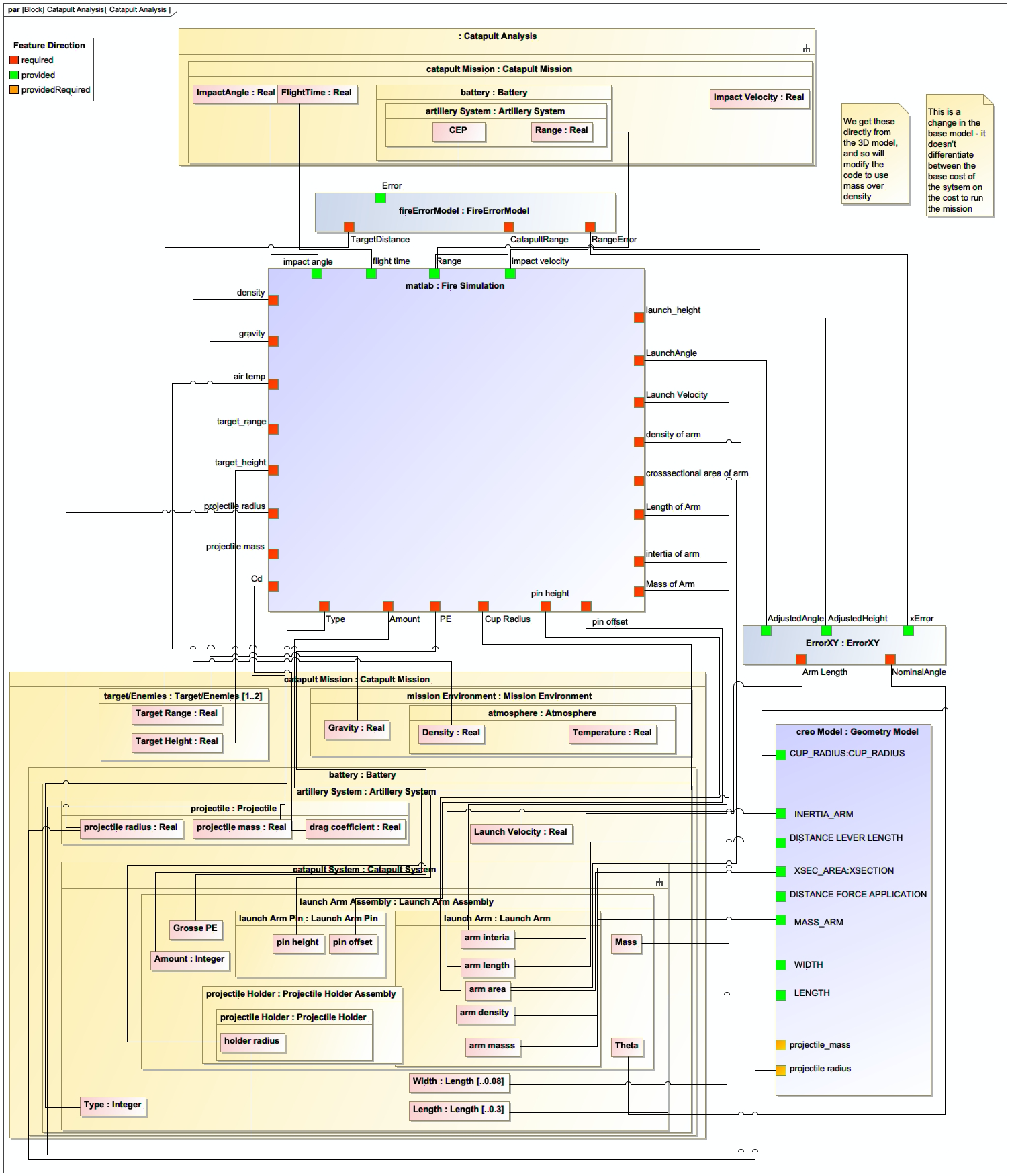
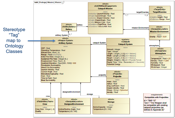
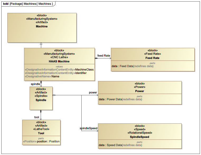
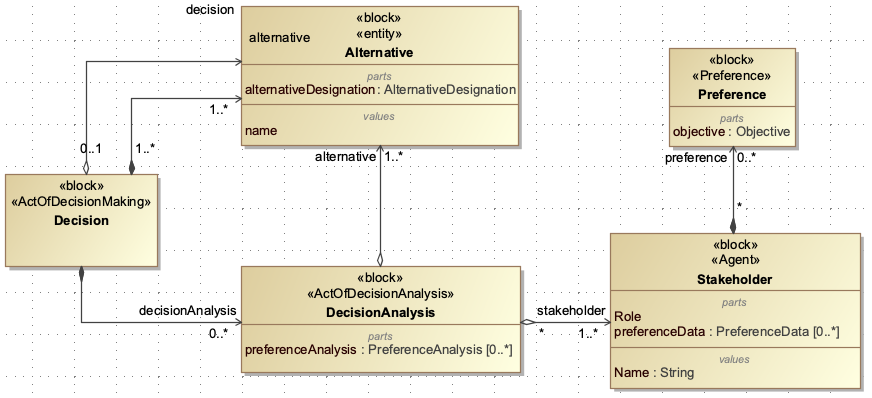
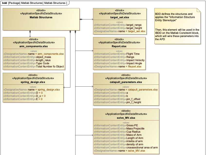
IBDs are closely related to other SysML diagram types: - Block Definition Diagrams (BDDs) define the high-level structure of the system (the "what") - Internal Block Diagrams (IBDs) define the internal structure and connections (the "how") - Parametric Diagrams are a specialized form of IBD that define mathematical relationships between parameters
| IBDs are not just visual representations; they are formal models that can be used for simulation, analysis, and integration with other engineering tools. |
Position in Knowledge Hierarchy
Broader concepts: - SysML (is-a)
Details
Internal Block Diagrams provide a detailed view of a system’s internal structure, including:
Element Type |
Description |
Part |
A component of the system, defined as a Block in the BDD |
Interface |
A connection point between parts, defined as an Interface Block |
Flow |
The material, energy, or information that moves between interfaces |
An IBD is created within a Block Definition Diagram (BDD) context, where the Block represents the system being modeled. The IBD then shows: 1. How the system Block is composed of other Blocks (parts) 2. How those parts connect through interfaces 3. The flows of materials, energy, or information between those interfaces
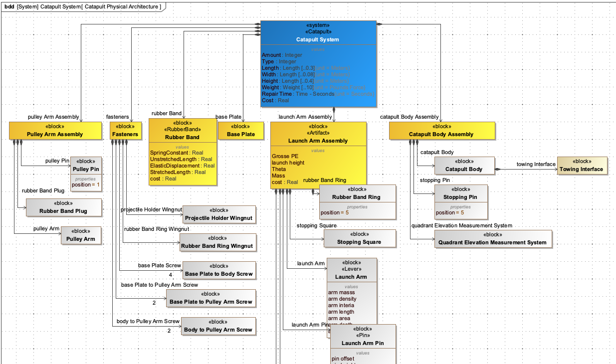
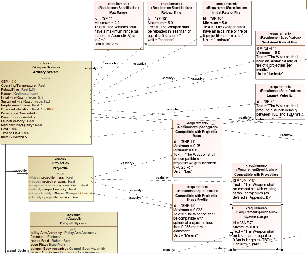
In the Catapult example from the handbook, the IBD would show: - The Catapult system (a Block in a BDD) - The Launch Arm Assembly as a part of the Catapult - The Launch Arm and Projectile as parts of the Launch Arm Assembly - Interfaces between the Launch Arm and other components - Flows like force between the Launch Arm and Base
| IBDs must accurately represent the physical and functional relationships within the system. Poorly designed IBDs can lead to integration issues when connecting with other models or simulations. |
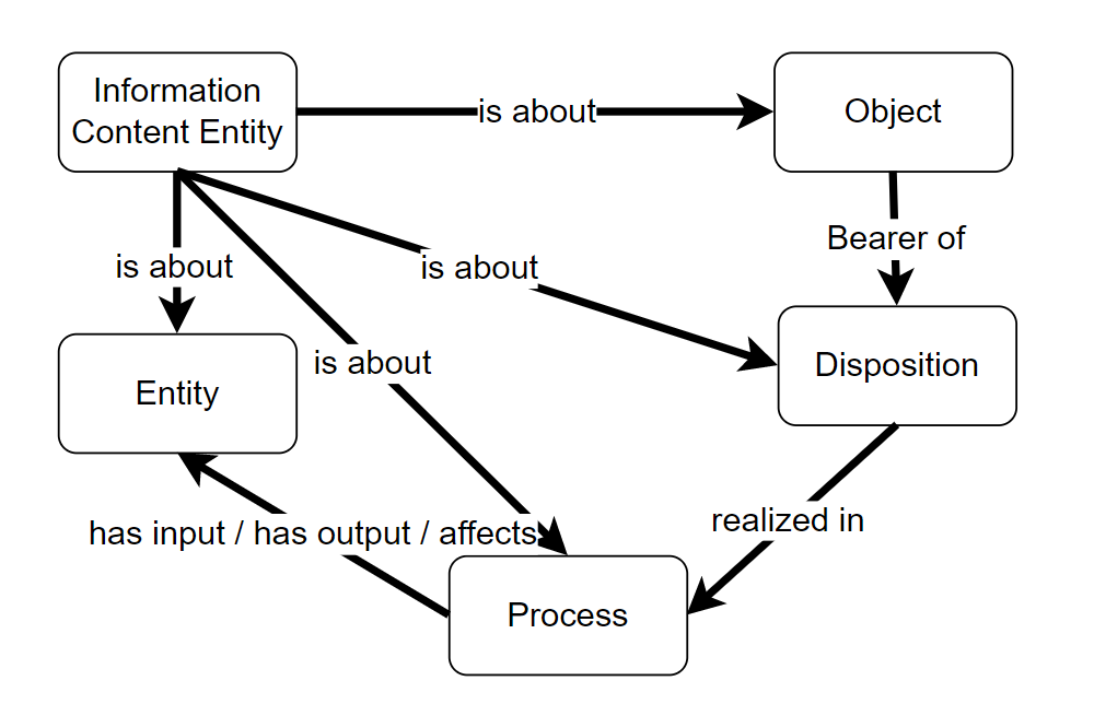
| When creating IBDs for IoIF workflows, ensure that all interfaces are properly defined with the appropriate metadata to support ontology alignment and data exchange. |
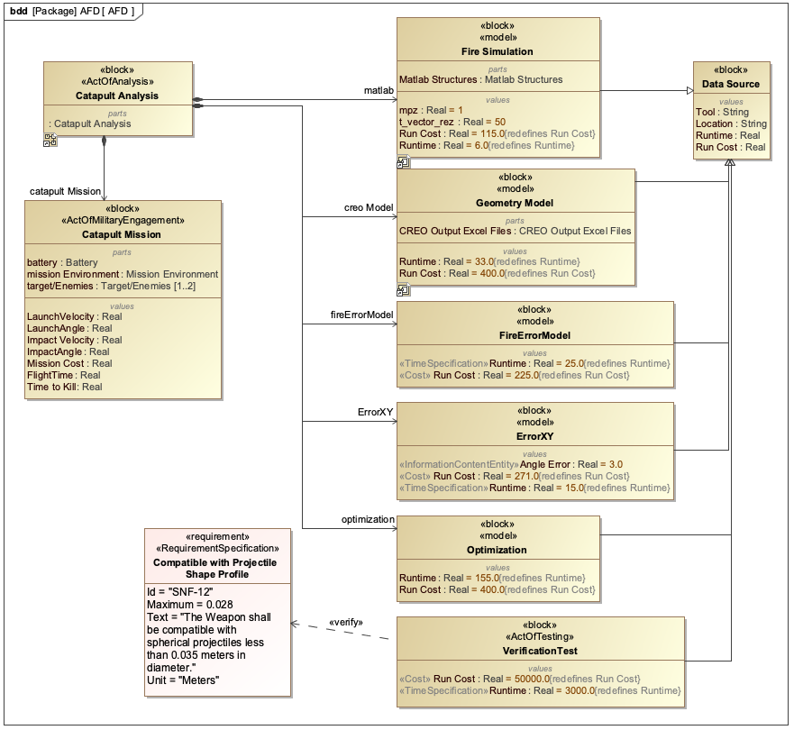
Practical applications and examples
The Catapult example from the handbook demonstrates how IBDs are used in practice:
This IBD shows: - The Catapult system (A) is composed of a Launch Arm Assembly (B) - The Launch Arm Assembly (B) has two parts: Launch Arm © and Projectile (D) - There’s a force flow from the Launch Arm © to the Base (E) - There’s a force flow from the Projectile (D) to the Launch Arm © - The Projectile (D) has a motion flow to the Target (F)
In the IoIF workflow, this IBD would be used to: 1. Define the interfaces for data exchange between different simulation tools 2. Specify the flows of data (like force, velocity) that need to be exchanged 3. Create a foundation for the Assessment Flow Diagram (AFD) that coordinates the different simulations
| The Catapult example in the handbook shows how IBDs are used to connect different types of analyses (e.g., geometry, ballistics, aerodynamics) through standardized interfaces, enabling integrated trade space analysis. |
|
To create an IBD in a SysML tool like MagicDraw or Cameo Systems Modeler: 1. Open a Block Definition Diagram (BDD) 2. Create a Block representing the system (e.g., Catapult) 3. Right-click the Block and select "Create Internal Block Diagram" 4. Add parts (e.g., Launch Arm Assembly) as parts of the system 5. Add interfaces between parts 6. Define flows between interfaces |
Related wiki pages
References
Knowledge Graph
Visualize the relationships between IBD and related concepts
Associated Diagrams