Introduction
The Digital Thread is a persistent data lineage that connects all phases of a system’s lifecycle—from design and manufacturing to operation and maintenance—ensuring data integrity and traceability across the entire development process.
| The Digital Thread is not a single tool or technology, but a concept that enables seamless data flow and integration across the entire system lifecycle, allowing stakeholders to make informed decisions based on consistent, up-to-date information. |
Overview
The Digital Thread represents the continuous flow of data and information throughout a system’s lifecycle, connecting design, development, testing, manufacturing, and operational phases. It enables traceability, data consistency, and informed decision-making by maintaining a persistent record of system evolution and its associated data.
The Digital Thread is implemented through the DEFII (Digital Engineering Framework for Integration and Interoperability) framework, which provides a structured approach to integrating diverse models and data sources. Within DEFII, the Digital Thread is supported by the IoIF (Armaments Interoperability and Integration Framework), which coordinates data exchanges between different tools and models.
| The Digital Thread is a key enabler of Digital Engineering (DE), allowing organizations to move from document-centric to model-centric engineering practices. |
| Digital Thread implementation requires careful planning and governance to ensure data quality, consistency, and interoperability across the entire system lifecycle. |
Position in Knowledge Hierarchy
Broader concepts: - Part I (is-a)
Details
The Digital Thread is implemented through a layered approach that connects different phases of the system lifecycle using ontology-aligned data and semantic technologies. The key components include:
Digital Thread Architecture
The Digital Thread architecture is built upon the DEFII framework, which provides three layers of components:
| Layer | Description |
|---|---|
Ontology-Aligned Data |
Foundation of the framework with data aligned to ontologies (e.g., BFO, CCO) |
Automated Reasoning |
Enriches data using axioms and rules defined in ontologies |
Tool Proxy Interface Types |
Three categories for interfacing with ontology-aligned data: Direct, Mapping, and Specified Model Interfaces |
The three tool proxy interface types enable flexible access to ontology-aligned data regardless of the tool accessing the data:
| Interface Type | Description |
|---|---|
Direct Interface |
Direct invocation of SWT stack (e.g., SPARQL queries) |
Mapping Interface |
Tool-dependent mapping from tool-specific representations to ontologies |
Specified Model Interface |
Tool-independent access to ontology-aligned data |
Digital Thread Implementation
The Digital Thread is implemented through the IoIF workflow, which coordinates data exchanges between different modeling and simulation tools. The workflow typically follows these steps:
-
Initialize with a REST GET from Teamwork Cloud (TWC), loading the SysML model with the Assessment Flow Diagram (AFD)
-
Pull model data (e.g., from Creo, which may require CSV exports)
-
Run simulations using data from the IoIF repository
-
Send results back to the IoIF repository using REST PUT
-
Visualize results in dashboards (Decision Dashboard, Digital Thread Impact Analysis)
|
For practical implementation, use Jupyter Notebooks to coordinate the workflow, as they allow different SMEs to collaborate on different aspects of the analysis (e.g., geometry modeling, ballistic simulation). |
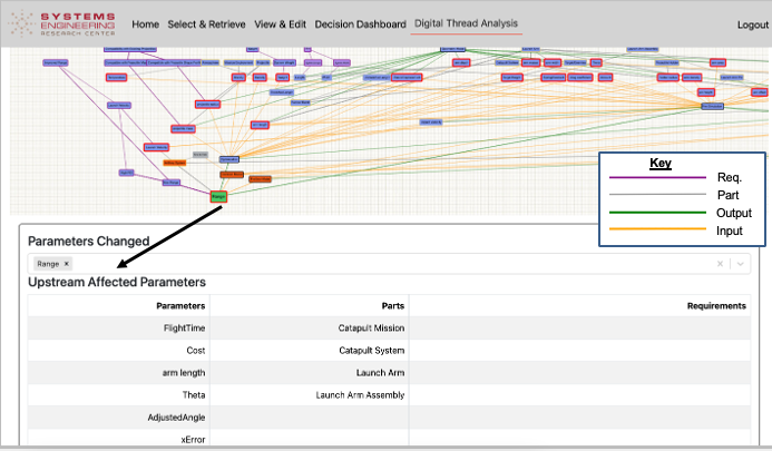
Digital Thread Impact Analysis
The Digital Thread Impact Analysis dashboard provides a visual representation of how changes to parameters affect the system. It uses color-coding to indicate different entities and their relationships:
| Entity | Color Coding |
|---|---|
Parameters |
Gray |
System Parts |
Yellow |
Requirements |
Purple |
Models |
Black |
Connectors (Input) |
Yellow |
Connectors (Output) |
Green |
Selected Parameters |
Red Outline |
When a parameter is selected, the dashboard calculates and visualizes: - Upstream parameters: Those that feed into the selected parameter - Downstream parameters: Those affected by the selected parameter - Unaffected nodes: Those with no relation to the selected parameter
| The Digital Thread Impact Analysis is "naïve" in that it’s based solely on the connections described in the model rather than a physical understanding of the system. More sophisticated implementations could use a more expressive ontology to consider physical relationships. |
Practical applications and examples
The Catapult use case provides a concrete example of Digital Thread implementation:
| The Catapult example demonstrates how the Digital Thread enables analysis of different variants (e.g., Analysis as Designed, Analysis as Manufactured, Analysis Configuration Changed, Analysis Requirement Changed). |
Catapult Digital Thread Workflow
-
Initialization: The workflow starts with a REST GET from Teamwork Cloud to load the SysML model with the AFD
-
Data Extraction: The Creo model is pulled into the IoIF as a CSV file (since Creo lacks an API)
-
Simulation Execution:
-
Operator Aiming simulation pulls data from IoIF via REST GET, runs in Python, and sends results back via REST PUT
-
Ballistic simulation pulls data from IoIF via MATLAB webread, runs simulation, and sends results back via MATLAB webwrite
-
-
Visualization: Results are rendered in the Digital Thread Impact Analysis dashboard
Associated Diagrams