Introduction
SysML is a standardized modeling language used to design and analyze complex systems. It provides a visual way to describe system structure, behavior, requirements, and constraints, making it easier for engineers to communicate and collaborate on system design.
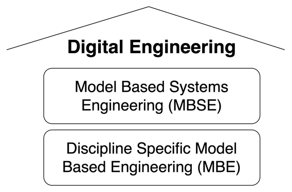
| SysML is a key tool in Model-Based Systems Engineering (MBSE), helping teams move away from document-based systems engineering toward model-based approaches. |
Overview
SysML (Systems Modeling Language) is a general-purpose modeling language for specifying, analyzing, designing, and verifying complex systems. It extends the Unified Modeling Language (UML) with additional constructs specifically tailored for systems engineering. SysML is widely used in MBSE to create descriptive models that define system structure, behavior, requirements, and constraints.
SysML v1 has been around for about 20 years, with SysML v2 nearing standardization by the Object Management Group (OMG). The language is particularly valuable for digital engineering (DE) as it enables the creation of models that can be aligned with ontologies for interoperability.
| SysML is not the same as MBSE - MBSE is the broader methodology that uses modeling languages like SysML to support systems engineering activities. |
The SysML language has four main pillars that support different aspects of system modeling:
Pillar |
Description |
Structure |
Describes system components, their relationships, and interfaces |
Behavior |
Describes how the system operates, including sequences and states |
Parametrics |
Defines mathematical relationships between system parameters |
Requirements |
Specifies what the system must do or achieve |
Position in Knowledge Hierarchy
Broader concepts: - Part II (is-a)
Narrower concepts: - BDD (is-a) - IBD (is-a) - Parametric Diagram (is-a)
Details
SysML Diagram Types
SysML supports multiple diagram types that help engineers visualize different aspects of a system. The main diagram types include:
Diagram Type |
Purpose |
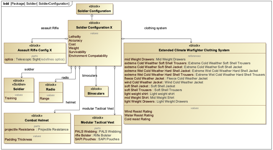
Block Definition Diagram (BDD) |
Shows structural decomposition of a system into blocks and their relationships |
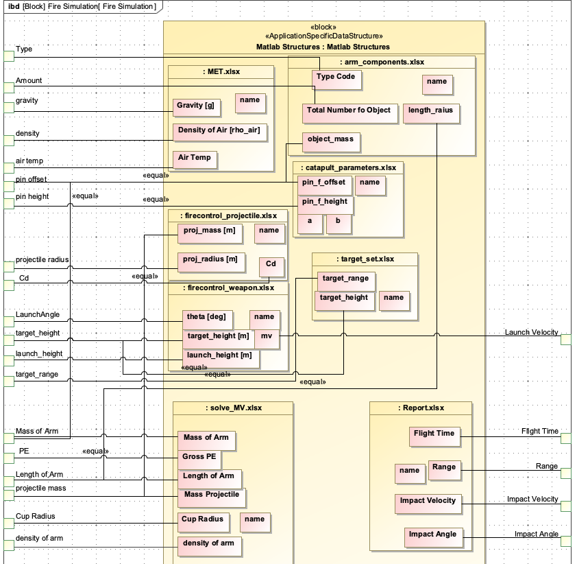
Internal Block Diagram (IBD) |
Shows parts, interfaces, and flows within a block |
Activity Diagram |
Describes control and data flow of asynchronous activities |
Sequence Diagram |
Shows interactions among distributed objects or services via sequences of messages |
State Machine Diagram |
Describes sequences of states that an object or interaction goes through |
Parametric Diagram |
Specialized Internal Block Diagram enforcing mathematical rules across properties |
Requirement Diagram |
Defines requirements and their relationships |
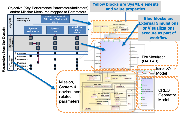
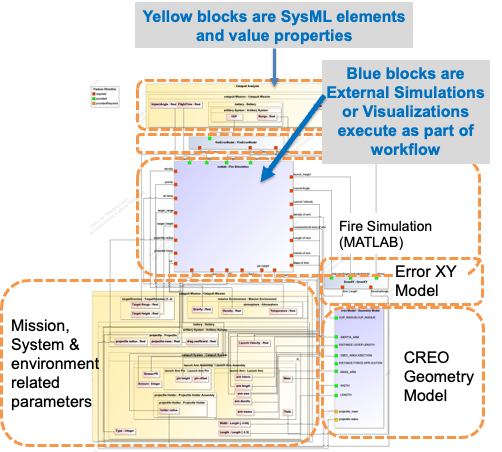
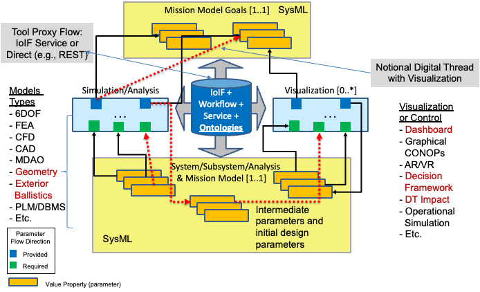
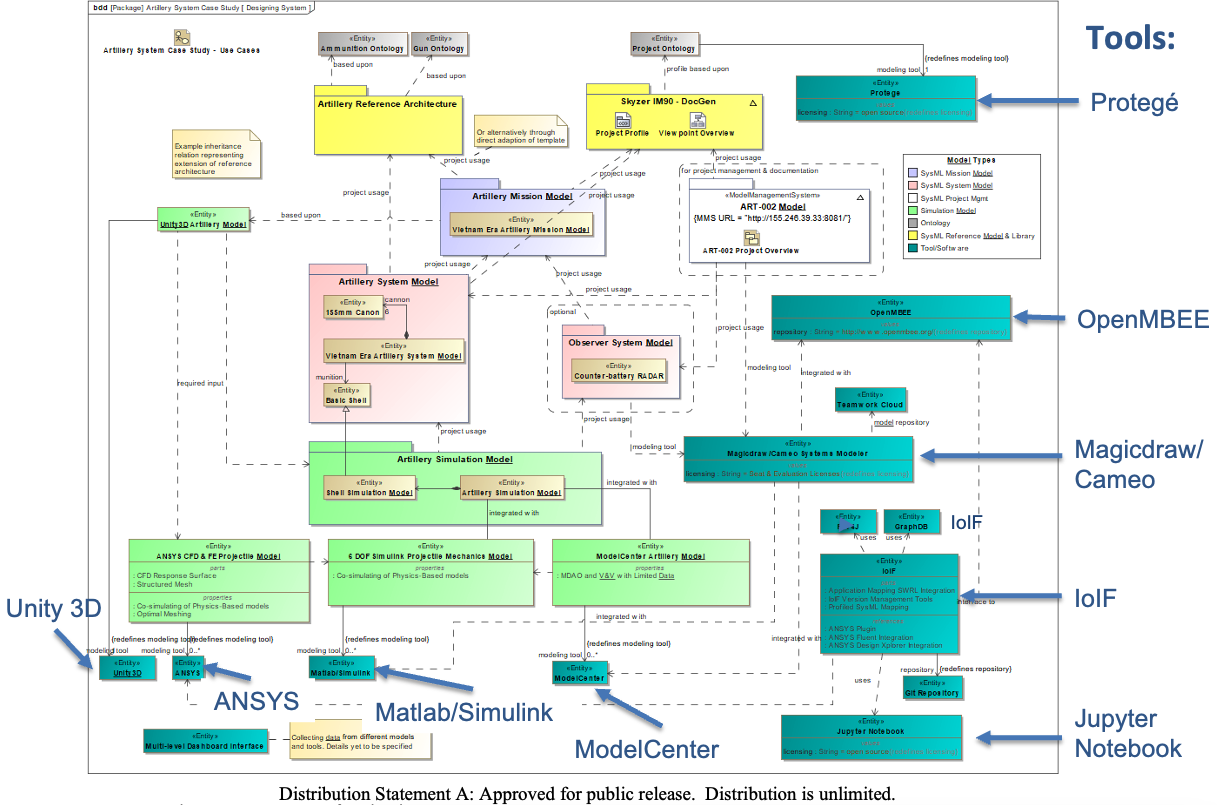
SysML in the Digital Engineering Context
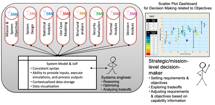
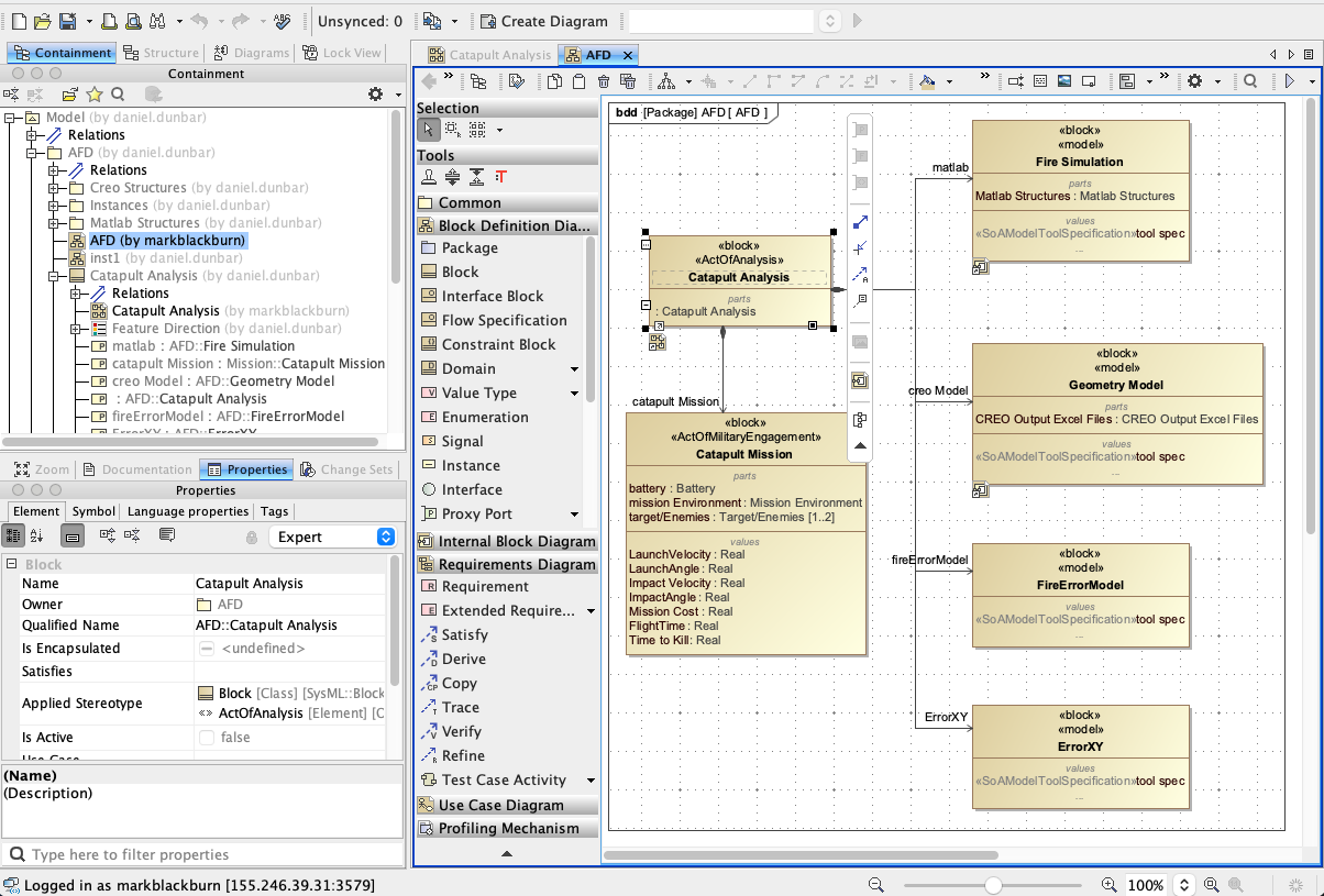
In the context of digital engineering and the Armaments Interoperability and Integration Framework (IoIF), SysML serves as the foundation for creating descriptive models that can be aligned with ontologies. The IoIF framework uses SysML models to configure workflows for cross-domain analysis.
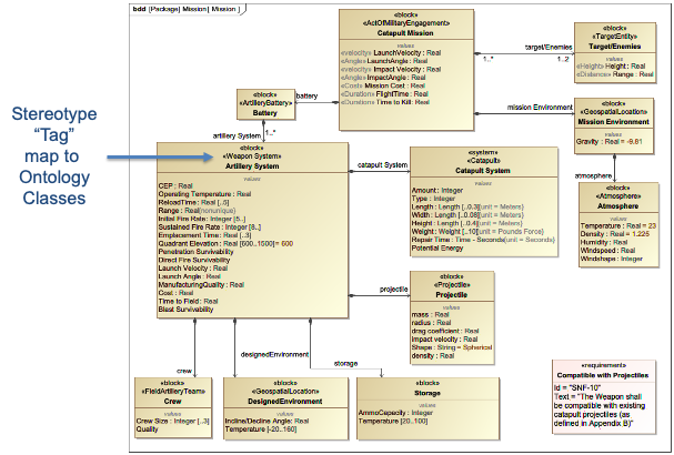
| SysML models must be properly structured and tagged with ontology metadata to work effectively with IoIF. This tagging is typically done using SysML stereotypes. |
The following example shows how SysML blocks and properties are used to represent a catapult system:
block Catapult {
  property launchArm : LaunchArm;
  property projectile : Projectile;
  property maxRange : Real = 4.0; // In meters
}

block LaunchArm {
  property length : Real;
  property mass : Real;
  property springConstant : Real;
}

block Projectile {
  property mass : Real;
  property diameter : Real;
}
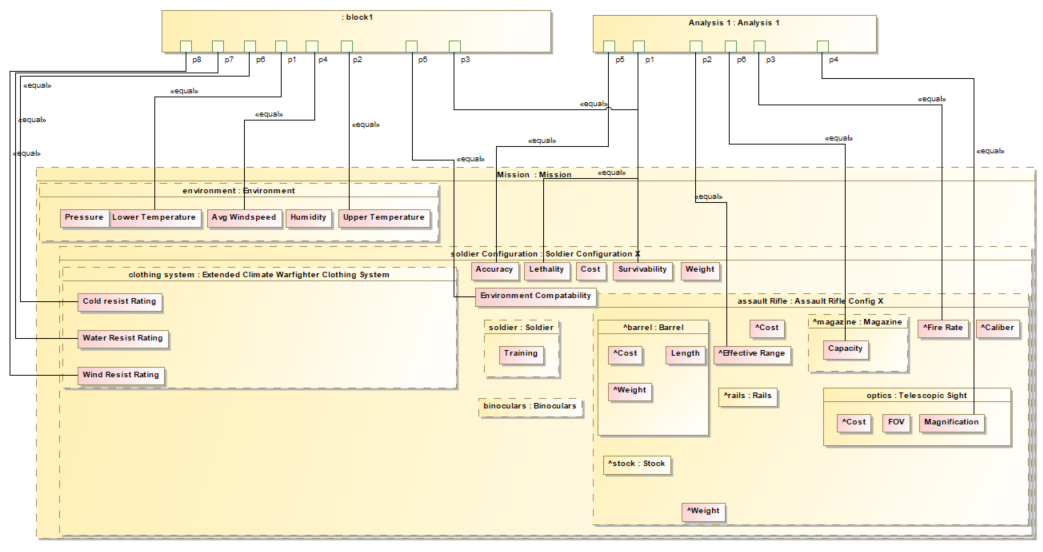
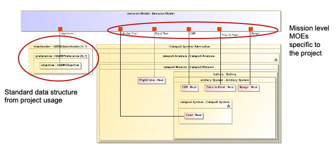
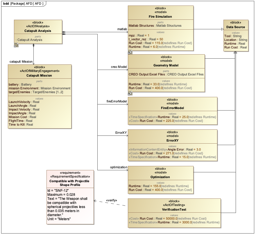
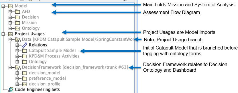
In the Catapult example, the maxRange property is a value property that represents a mission objective. This property is used in the Assessment Flow Diagram (AFD) to calculate performance metrics.
|
Ontology Alignment with SysML
SysML models can be aligned with ontologies using metadata, typically through stereotypes. This alignment allows the models to be integrated with IoIF for cross-domain analysis.
| The metadata must be applied consistently and unambiguously to ensure IoIF can correctly interpret the model elements. |
The following example shows how a SysML block can be tagged with ontology metadata:
<<catapult>> block Catapult {
  property maxRange : Real = 4.0;
  property impactAngle : Real;
}
In this example, the [catapult] stereotype indicates that the Catapult block corresponds to a class in the Catapult ontology.
| Without proper ontology alignment, IoIF cannot effectively integrate the SysML model with other domain-specific models and analyses. |
Practical applications and examples
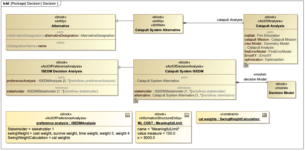
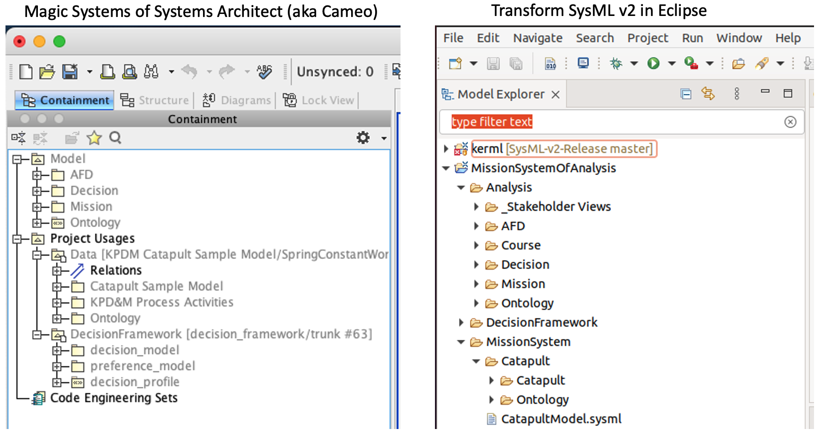
Catapult Case Study
The Catapult case study demonstrates how SysML is used in digital engineering workflows. The SysML model includes:
-
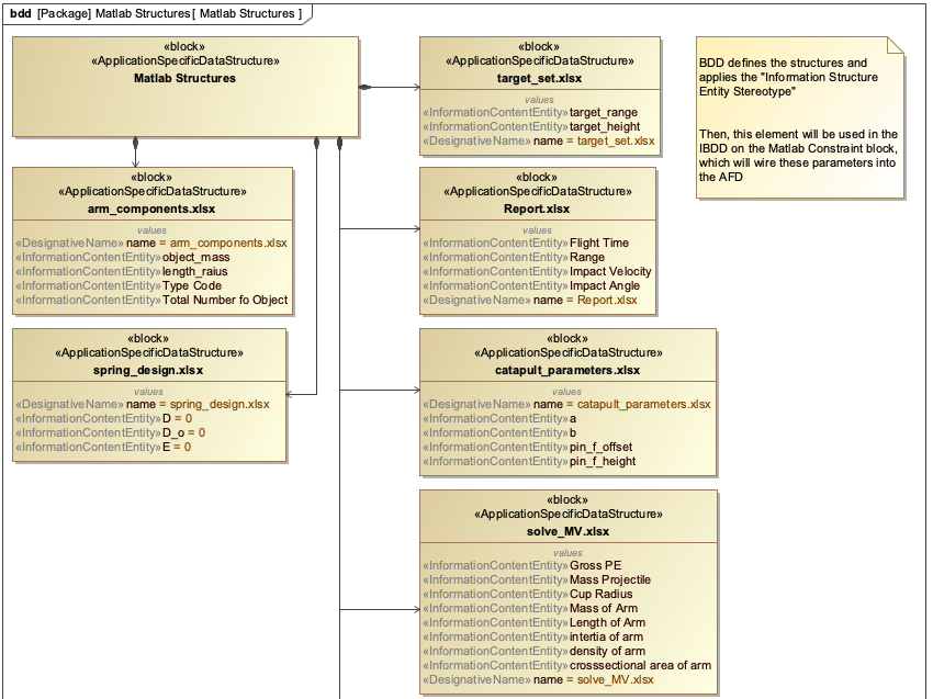
A Block Definition Diagram (BDD) showing the structural decomposition of the catapult system
-
An Internal Block Diagram (IBD) showing the internal components and interfaces
-
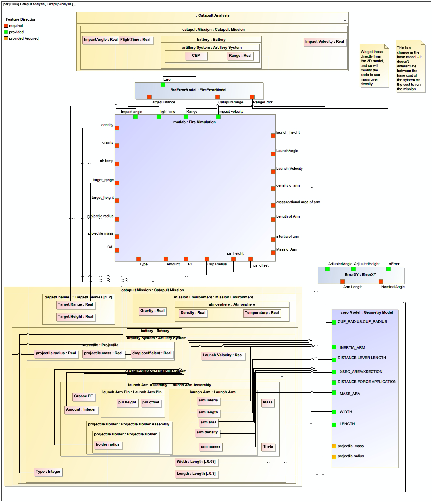
A Parametric Diagram (AFD) showing the mathematical relationships between parameters
Associated Diagrams