Introduction
A Block Definition Diagram (BDD) is a visual representation of a system’s structural decomposition, showing how a system is composed of its main components and their relationships. It’s like a blueprint that reveals the fundamental building blocks of a system.
Overview
Block Definition Diagrams (BDDs) are one of the four primary diagram types in the Systems Modeling Language (SysML), used extensively in Model-Based Systems Engineering (MBSE). BDDs provide a high-level view of a system’s structure, showing the main blocks (components) and their relationships. They serve as the foundation for all other modeling activities, enabling clear communication about system architecture before diving into detailed behavior or parametric analysis.
BDDs are essential for: - Establishing the system’s structural context - Defining the main components and their relationships - Providing the basis for detailed internal block diagrams - Supporting ontology alignment for semantic interoperability
|
BDDs are foundational to MBSE and provide the structural context for all other modeling activities. Without a well-defined BDD, it’s difficult to create accurate IBDs, parametric diagrams, or other system models. |
Position in Knowledge Hierarchy
Broader concepts: - SysML (is-a)
Details
BDDs represent the system’s structure through blocks and their relationships. A block can represent a physical component, a subsystem, or even a concept. Blocks have two main types of properties:
-
Value properties: Characteristics or attributes of a block (e.g., length, mass, color)
-
Part properties: Components or sub-blocks that make up the block (e.g., frame, launch arm assembly)
In SysML, BDDs are used to establish the main structural decomposition of a system, which informs the creation of other diagram types like Internal Block Diagrams (IBDs) and Parametric Diagrams.
|
When creating BDDs, use clear and descriptive names for blocks, properties, and relationships to ensure readability and maintainability of the model. This is especially important when aligning the model with ontologies for semantic interoperability. |
BDD Structure and Components
A BDD consists of:
-
Blocks: Represent system components (e.g., Catapult, Launch Arm Assembly)
-
Relationships: Show how blocks are connected (e.g., composition, aggregation)
-
Properties: Value properties (characteristics) and part properties (subcomponents)
Block Type |
Description |
Block |
Represents a system component, subsystem, or concept |
Value Property |
Characteristic or attribute of a block (e.g., length, mass) |
Part Property |
Sub-component or sub-block that makes up a block |
BDD in Ontology Alignment
When using BDDs for ontology alignment (as in the IoIF framework), blocks and properties are tagged with stereotypes that map to ontology classes. This allows the model to be integrated with semantic technologies.
For example: - "Catapult" might be tagged with [Catapult] - "Launch Arm Assembly" might be tagged with [LaunchArmAssembly] - "Length" might be tagged with [Length]
This tagging enables the model to be used in workflows like the Assessment Flow Diagram (AFD), where the ontology-aligned data can be used for computational reasoning and interoperability.
|
Avoid creating overly complex BDDs with too many levels of decomposition at the outset. Start with the high-level structure and add detail as needed for the specific analysis or modeling purpose. |
Practical applications and examples
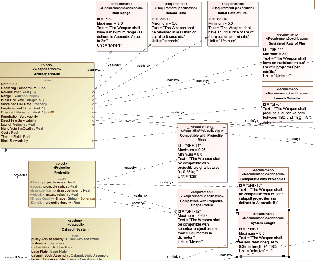
Let’s examine the Catapult example from the handbook to see how BDDs are used in practice:
-
Start with the main system block: "Catapult"
-
Add part properties to represent major components:
-
"Launch Arm Assembly"
-
"Frame"
-
"Projectile"
-
-
For each part, add value properties:
-
"Launch Arm Assembly" has value properties: "Length", "Mass"
-
"Projectile" has value properties: "Mass", "Diameter"
-
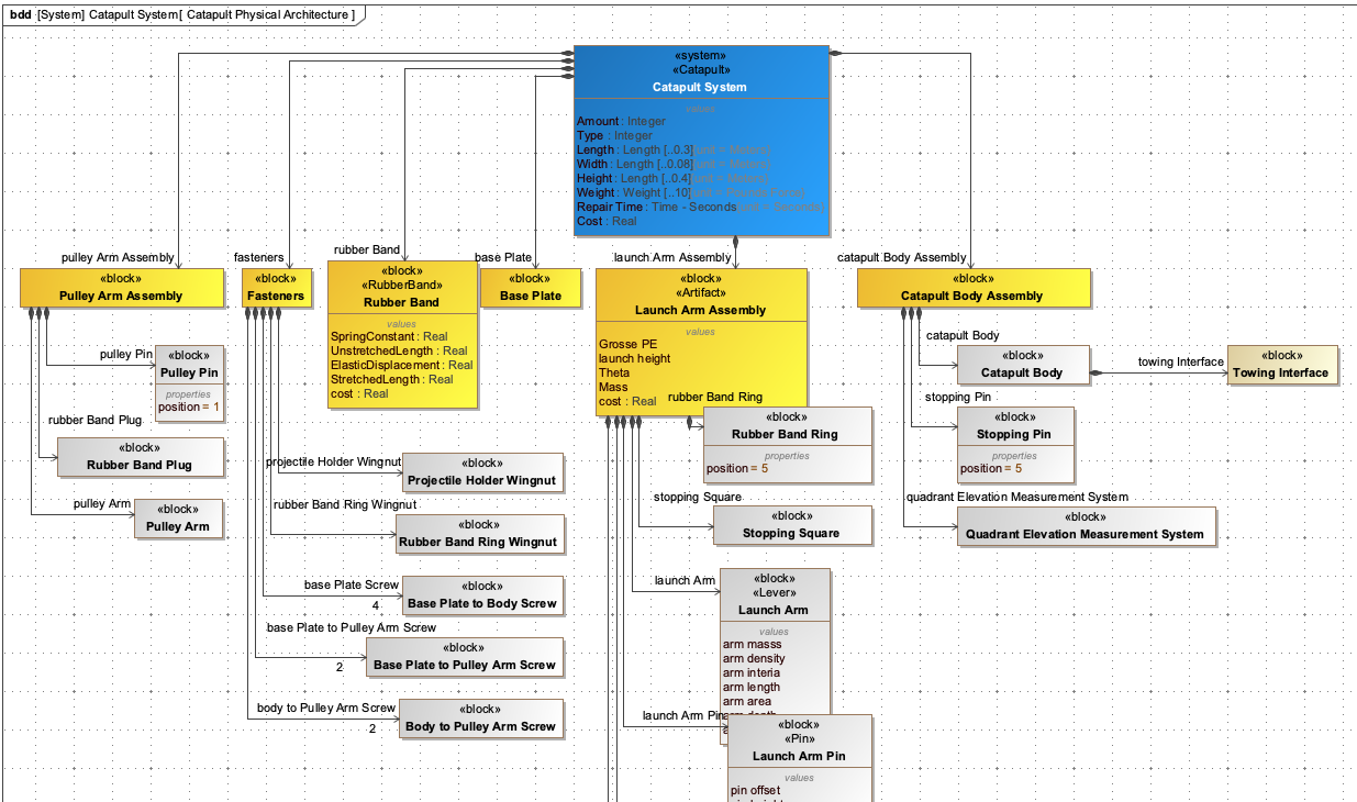
Here’s a visual representation of the Catapult BDD:
This BDD can be extended to include more detail as needed for the analysis. For example, the "Launch Arm Assembly" might be further decomposed into "Arm", "Spring", and "Trigger Mechanism" blocks.
|
The Catapult BDD shown here is a simplified example. In a real-world scenario, the BDD would be more detailed and would include the appropriate stereotypes for ontology alignment as shown in Figure 44 of the context. |
|
When using BDDs with the IoIF framework, the stereotypes applied to blocks and properties are critical for the tool proxies to correctly map the model elements to the ontology classes. This ensures that the data can be properly integrated into the semantic triplestore for computational reasoning. |
Related wiki pages
References
Knowledge Graph
Visualize the relationships between BDD and related concepts
Associated Diagrams