Introduction
MBSE is a modern engineering approach that uses visual and mathematical models instead of documents to design, analyze, and verify complex systems. It helps engineers think through all system components and their interactions before physical implementation.
|
MBSE is not a tool or a specific methodology—it’s a paradigm that formalizes the use of modeling throughout the entire systems engineering lifecycle. |
Overview
MBSE (Model-Based Systems Engineering) is the formalized application of modeling to support system requirements, design, analysis, verification, and validation activities beginning in the conceptual design phase and continuing throughout development and later lifecycle phases. It’s a paradigm that encompasses many methodologies, tools, and languages.
MBSE fundamentally differs from traditional document-based systems engineering by creating a single, integrated model that serves as the authoritative source of truth for the system. This model supports multiple views for different stakeholders and can be used for analysis, simulation, and automated documentation.
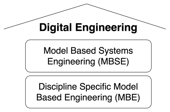
| MBSE is a key component of the Digital Engineering (DE) ecosystem, which integrates modeling, simulation, and data across the entire product lifecycle. |
The MBSE paradigm has evolved to address the increasing complexity of modern systems, enabling better communication, reduced errors, and more efficient decision-making throughout the engineering process.
|
MBSE is not synonymous with SysML. While SysML is a common language used in MBSE, MBSE is the broader methodology that can use multiple modeling languages and tools. |
Position in Knowledge Hierarchy
Broader concepts: - Digital Engineering (is-a)
Details
MBSE vs. MBE
MBSE and MBE (Model-Based Engineering) are related but distinct concepts within the broader Digital Engineering ecosystem:
| Category | MBSE |
|---|---|
Focus |
System-level, cross-disciplinary |
Primary Models |
Descriptive models (structure, behavior, requirements) |
Key Use Cases |
System architecture, interfaces, requirements traceability |
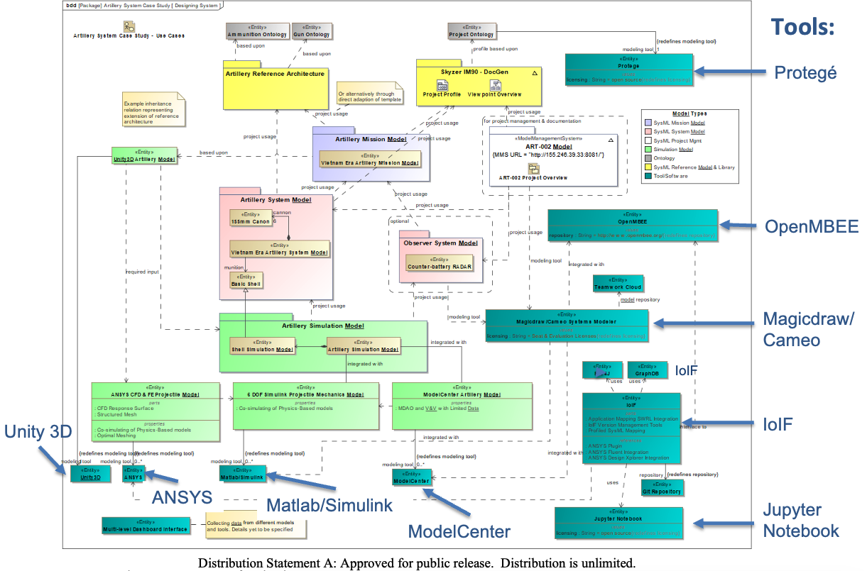
Typical Tools |
SysML tools (MagicDraw, Cameo Systems Modeler) |
Data Representation |
Whole-part relationships, functional decomposition |
Example |
Catapult system architecture showing relationships between components |
Category |
MBE |
Focus |
Discipline-specific (mechanical, electrical, software) |
Primary Models |
Analysis and simulation models |
Key Use Cases |
Finite Element Analysis (FEA), Computational Fluid Dynamics (CFD) |
Typical Tools |
ANSYS, MATLAB, Simulink |
Data Representation |
Mathematical relationships, physical properties |
Example |
Aerodynamic analysis of a catapult arm |
| The key distinction: MBSE focuses on how the system works as a whole (the "what" and "how"), while MBE focuses on how specific parts work (the "how" at a detailed level). |
MBSE Methodology and Tools
MBSE methodology involves creating a set of descriptive models that represent the system at various levels of abstraction. The most common modeling language for MBSE is SysML, which provides a comprehensive set of diagram types to represent system structure, behavior, and requirements.
The four pillars of SysML (used in MBSE) include:
-
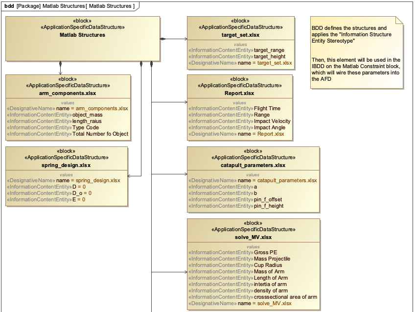
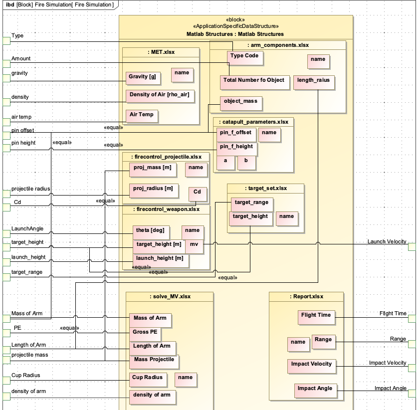
Structure: Block Definition Diagrams (BDD) and Internal Block Diagrams (IBD)
-
Behavior: Activity Diagrams, State Machine Diagrams
-
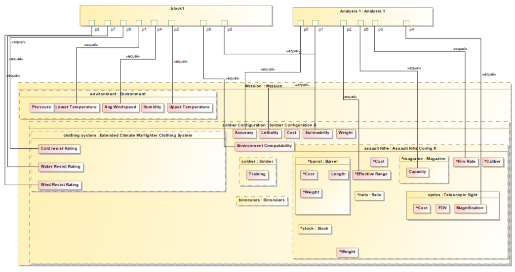
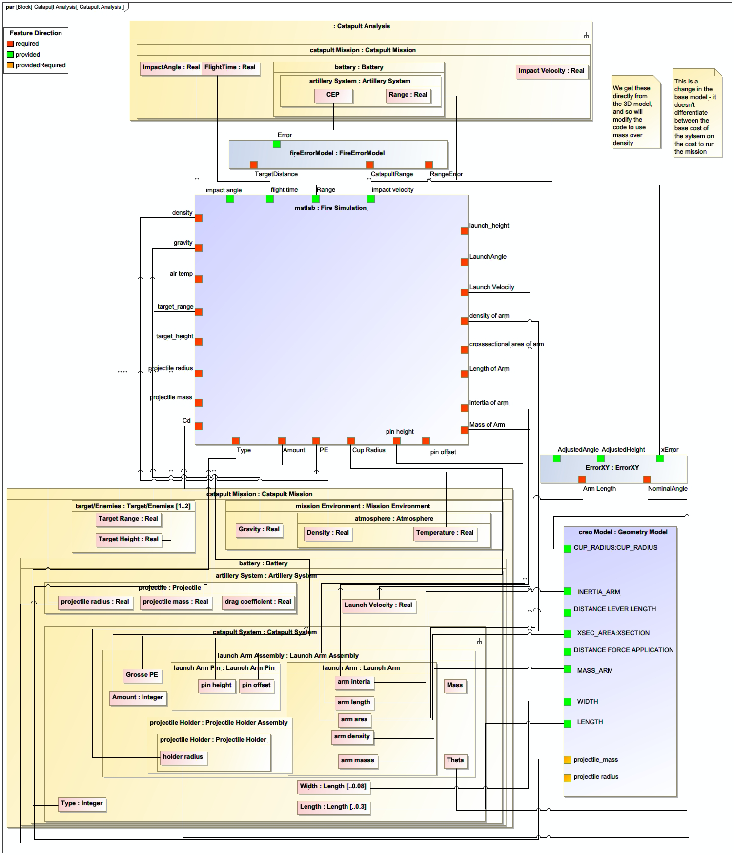
Parametrics: Parametric Diagrams for mathematical relationships
-
Requirements: Requirements Diagrams for traceability
|
SysML v2 is nearing standardization by the Object Management Group (OMG) and is designed to better support the needs of MBSE workflows compared to SysML v1. |
Creating MBSE Models
Creating effective MBSE models requires careful planning and adherence to best practices:
-
Start with a Concept of Operation (CONOP) to understand the operational context
-
Define system boundaries and key stakeholders
-
Create a Block Definition Diagram (BDD) to define system structure
-
Add Internal Block Diagrams (IBDs) to show component relationships
-
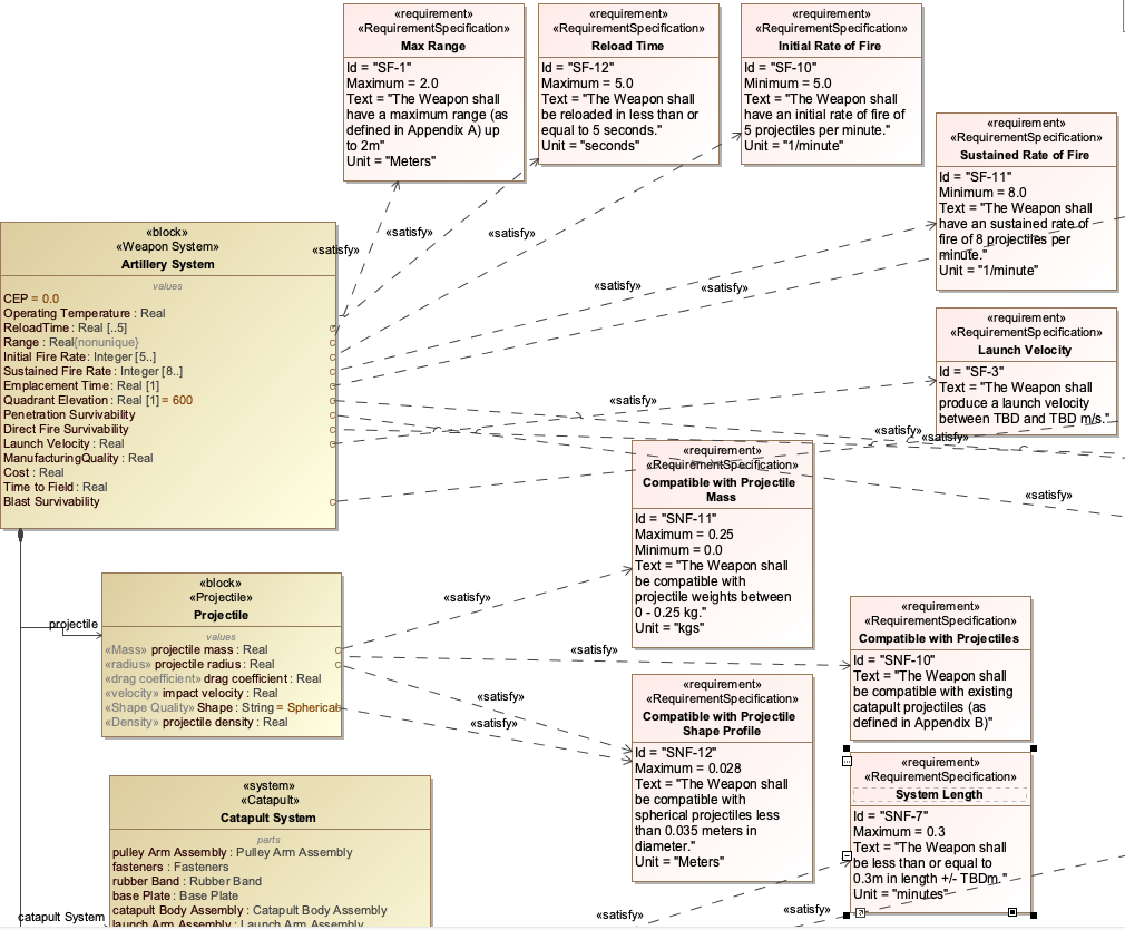
Define requirements and connect them to system elements
-
Use parametric diagrams for quantitative analysis
| Use clear and descriptive names for your SysML blocks, properties, and OWL classes to ensure readability and maintainability. |
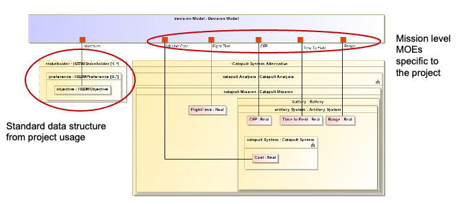
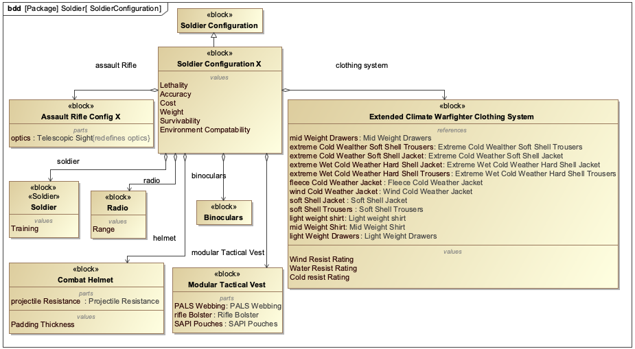
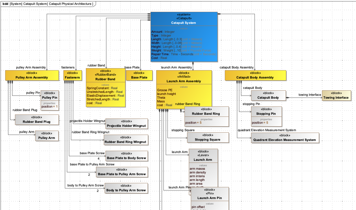
Example: Catapult System Modeling
The Catapult case study demonstrates MBSE in action:
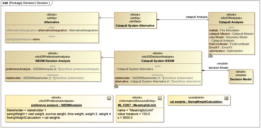
| In the Catapult example, the MBSE model includes: - System structure (BDD showing components) - Component relationships (IBD) - Quantitative relationships (parametric diagram) - Mission objectives (range, impact velocity) |
Practical applications and examples
Implementing MBSE with IoIF
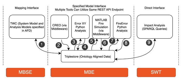
The Armaments Interoperability and Integration Framework (IoIF) demonstrates how MBSE models integrate with semantic technologies:
-
Start with a SysML model of the system (e.g., Catapult)
-
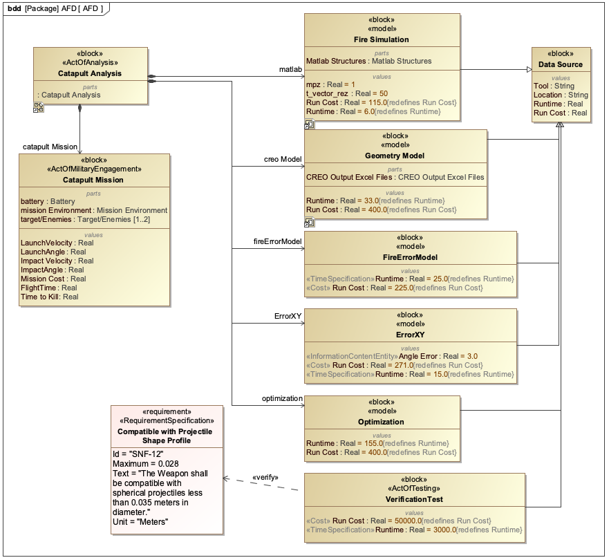
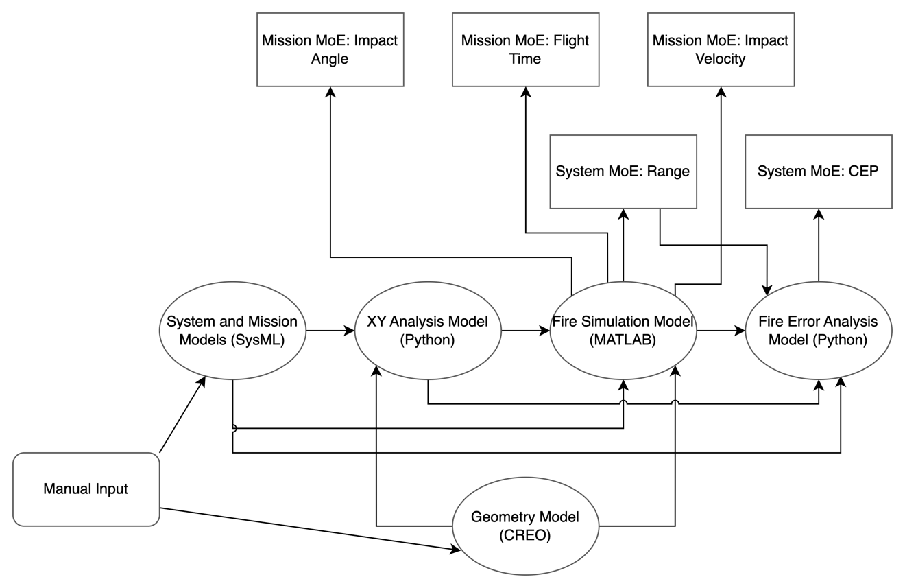
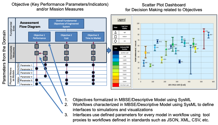
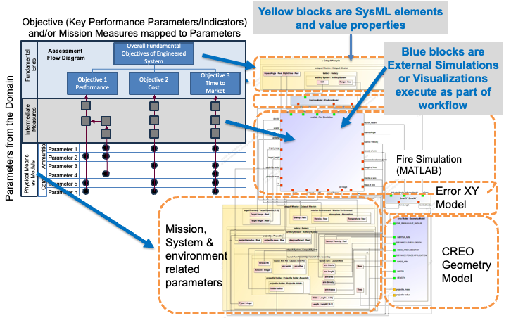
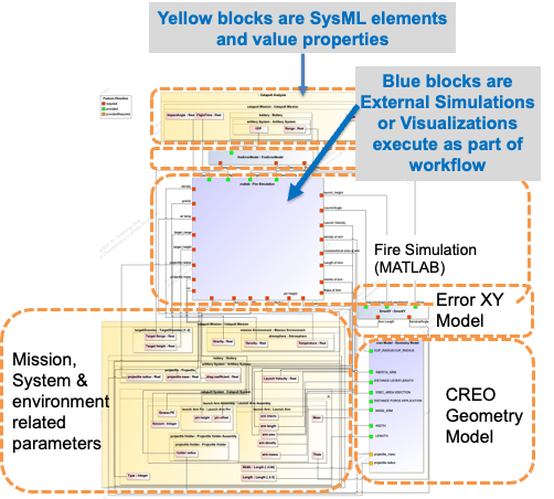
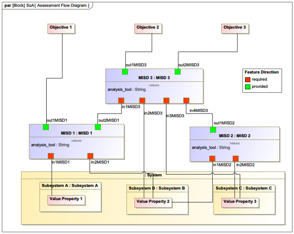
Add an Assessment Flow Diagram (AFD) to define analysis relationships
-
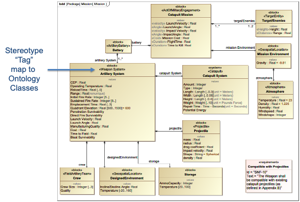
Use stereotypes to align model elements with ontology classes
-
Configure IoIF with the SysML model and AFD
-
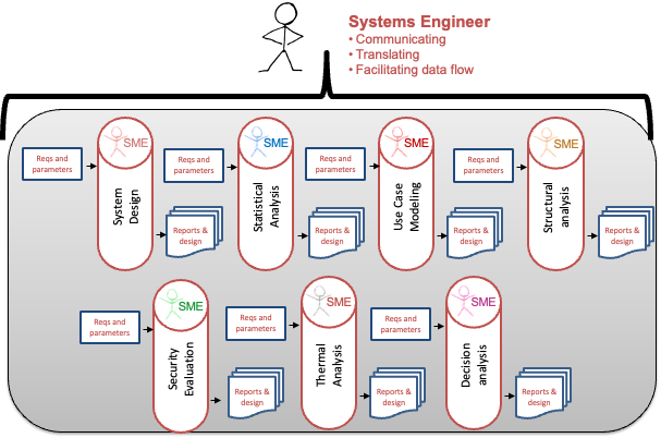
Run analysis workflows that connect different simulation tools
| The IoIF framework leverages MBSE models to "configure" ontology-aligned data, hiding the complexity of ontologies from typical users. |
Step-by-Step MBSE Workflow
Here’s a practical example of implementing MBSE using SysML and IoIF:
|
This example assumes you have SysML modeling tools (like Cameo Systems Modeler) and IoIF installed. |
-
Create the System Model:
-
Use a Block Definition Diagram (BDD) to define system components
-
Example: Create a "Catapult" block with properties like "Max Range" and "Launch Angle"
-
-
Define the Analysis Flow:
-
Create an Assessment Flow Diagram (AFD) showing relationships between parameters
-
Example: Connect "Launch Angle" to "Range" using a parametric equation
-
-
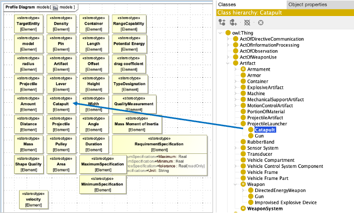
Tag Model Elements with Ontology Classes:
-
Apply stereotypes to model elements to indicate their ontology alignment
-
Example: Add
[CatapultSystem]stereotype to the Catapult block
-
-
Configure IoIF:
-
Load the SysML model with the AFD into IoIF
-
Configure the ontology alignment for the workflow
-
-
Run the Analysis:
-
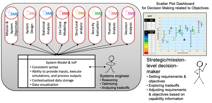
Execute the workflow using Jupyter Notebook or the Interactive Service Dashboard
-
Analyze trade-offs between different design parameters
-
= Example Python code for IoIF workflow configuration
from ioif import IoIF

= Initialize IoIF with ontology configuration
ioif = IoIF(
    ontologies=["bfo.owl", "catapult_ontology.owl"],
    model_path="catapult_model.sysml"
)

= Configure the workflow with the AFD
ioif.configure_workflow(
    afd_path="catapult_afd.sysml",
    analysis_types=["Analysis as Designed", "Analysis as Manufactured"]
)

= Execute the workflow
results = ioif.run_workflow()

= Visualize results in the Decision Dashboard
ioif.visualize_results("Decision Dashboard")|
The IoIF framework demonstrates how MBSE models serve as the "configuration" for semantic interoperability, allowing different tools to exchange data through ontology-aligned interfaces. |
Related wiki pages
References
Knowledge Graph
Visualize the relationships between MBSE and related concepts
Associated Diagrams