Introduction
Model-Based Engineering (MBE) is a technical approach where engineers use specialized computer models to analyze and design systems within specific engineering disciplines. Think of it as using precise mathematical and computational tools to solve problems in areas like mechanical, electrical, or software engineering.
Overview
MBE focuses on discipline-specific models that are mathematically grounded and used for analysis and design. Unlike broader system-level approaches, MBE concentrates on specific domains such as mechanical, electrical, or software engineering. These models typically use mathematical relationships to support quantifiable analysis about system parameters.
| MBE models are often used for analysis and design within a single engineering discipline, while MBSE (Model-Based Systems Engineering) operates at a higher level of abstraction to describe the overall system architecture and its components. |
The MBE paradigm has evolved alongside computational capabilities, enabling engineers to create increasingly sophisticated models that can be integrated into larger digital engineering ecosystems. MBE models form the foundation for many of the analysis tools used in the digital engineering workflow.
| MBE models are typically not designed for direct interoperability with other disciplines without additional integration frameworks like IoIF (Armaments Interoperability and Integration Framework), which provides the semantic layer for connecting discipline-specific models. |
Position in Knowledge Hierarchy
Broader concepts: - Digital Engineering (is-a)
Details
MBE vs. MBSE
MBE and MBSE represent different levels of abstraction in engineering modeling:
Level of Abstraction |
MBE |
MBSE |
Lower (Discipline-Specific) |
Focuses on specific engineering domains like mechanical, electrical, or software |
Focuses on system architecture, whole-part relationships, and interfaces |
Model Type |
Mathematical and analytical models |
Descriptive models (structure, behavior, requirements) |
Example |
Finite Element Analysis (FEA) for mechanical stress |
SysML Block Definition Diagrams (BDD) for system architecture |
Primary Use |
Analysis and design within a single discipline |
System integration, requirements management, and system-level verification |
Types of MBE Models
MBE models can be classified based on their mathematical approach:
Model Type |
Description |
Dynamic Models |
Describe time-varying states of a system (e.g., aircraft position, velocity, acceleration over time) |
Static Models |
Perform computations without representing time-varying states (e.g., mass properties estimate, reliability prediction) |
Analytical Models |
Use mathematical relationships to support quantifiable analysis (e.g., differential equations for stress analysis) |
MBE in the Digital Engineering Ecosystem
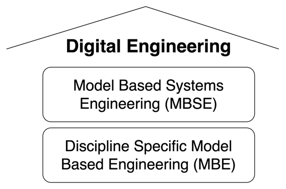
MBE models form the foundational layer of the digital engineering ecosystem, providing the discipline-specific analysis capabilities that feed into higher-level system models. As shown in Figure 11 from the context, MBE models are part of the "lower level" of the engineering modeling stack:
| MBE models are often mathematically rigorous and may have simulation environments. They represent the "bottom" of the modeling stack, providing the detailed analysis that feeds into higher-level system models. |
Practical applications and examples
Catapult Case Study Example
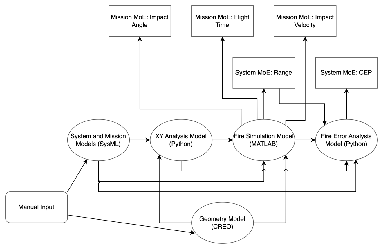
The Catapult case study from the context provides an excellent example of MBE in action. In this example, MBE models are used for:
-
Finite Element Analysis (FEA) - Analyzing mechanical stress on the catapult structure
-
Computational Fluid Dynamics (CFD) - Modeling aerodynamics of the projectile
-
Six Degree of Freedom (6DOF) Analysis - Simulating the projectile’s trajectory
-
Thermal Analysis - Modeling heat distribution in the catapult components
| The Catapult example demonstrates how MBE models provide the detailed analysis needed for system-level optimization. Each MBE model focuses on a specific discipline (mechanical, aerodynamic, thermal) and provides quantitative data that feeds into the higher-level MBSE models. |
Workflow Integration with IoIF
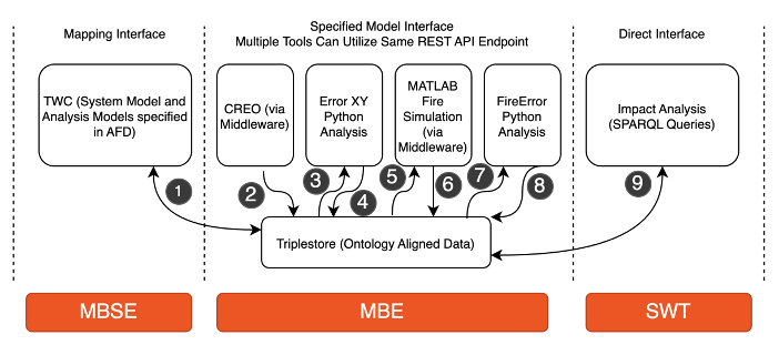
MBE models are integrated into the digital engineering workflow through the IoIF framework, which provides the semantic layer for interoperability between discipline-specific models:
Step |
Description |
1 |
MBE models (FEA, CFD, etc.) are created using discipline-specific tools |
2 |
IoIF uses tool proxies to extract data from these models |
3 |
Data is mapped to ontology-aligned format using metadata (e.g., SysML stereotypes) |
4 |
Data is stored in a triplestore repository |
5 |
IoIF coordinates data exchanges between models for analysis |
6 |
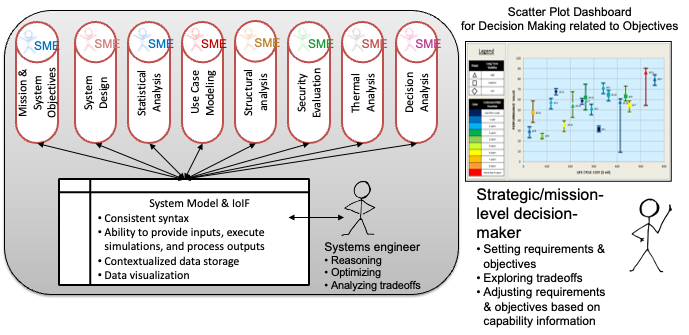
Results are visualized in dashboards (e.g., Decision Dashboard, Digital Thread Dashboard) |
|
To implement MBE models in your workflow: 1. Identify the discipline-specific analysis needs for your project 2. Select appropriate MBE tools (e.g., ANSYS for FEA, Fluent for CFD) 3. Create models using these tools 4. Use IoIF to integrate these models with higher-level MBSE models 5. Configure the system to use ontology alignment for interoperability |
Associated Diagrams