Introduction
A Measure of Effectiveness (MoE) is a quantitative metric used to evaluate how well a system or mission achieves its intended purpose. It provides objective data to assess performance against mission objectives.
Overview
MoE is a critical performance metric used in systems engineering to evaluate system effectiveness. It represents the actual measured values of performance criteria that directly relate to mission success. MoEs are distinct from Key Performance Parameters (KPPs), which define the minimum acceptable performance levels.
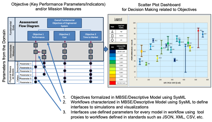
MoEs are essential for: - Supporting decision-making processes - Enabling trade-space analysis - Visualizing system performance against mission objectives - Providing data for the Digital Thread Impact Analysis
In the IoIF framework, MoEs are: - Defined in SysML models with ontology tags - Used as inputs to Assessment Flow Diagrams (AFDs) - Calculated through analysis models and simulations - Stored in ontology-aligned triplestore repositories - Visualized in Decision Dashboards for stakeholder review
|
MoEs must be directly tied to mission objectives to provide meaningful evaluation of system effectiveness. An MoE that doesn’t connect to a specific mission goal is not useful for decision-making. |
Position in Knowledge Hierarchy
Broader concepts: - KPP (is-a)
Narrower concepts: - CEP (is-a)
Details
MoEs are characterized by: - Quantitative nature (measurable values) - Direct relationship to mission objectives - Use in comparative analysis between design alternatives - Integration with ontology-aligned data for interoperability
In the context of Digital Engineering and IoIF, MoEs serve as the bridge between: 1. Mission objectives (expressed in the mission model) 2. System design (represented in the system model) 3. Analysis results (from discipline-specific models)
The relationship between MoE, KPP, and CEP is hierarchical: - MoE: General category of performance metrics - KPP: Minimum acceptable values for specific MoEs - CEP: A specific type of MoE for accuracy measurement
| MoEs are distinct from Measures of Performance (MoP), which evaluate system performance against specific tasks rather than overall mission effectiveness. |
Practical applications and examples
In the Catapult use case described in the handbook, the following MoEs are used to evaluate system performance:
MoE |
Description |
Example Value |
Impact Angle |
Angle at which the projectile impacts the target |
38 degrees |
Flight Time |
Duration from launch to impact |
8.2 seconds |
Impact Velocity |
Speed at impact |
55 m/s |
Range |
Distance from launch to impact |
520 meters |
CEP |
Circular Error Probability (accuracy measure) |
8 meters |
Cost |
Total development cost |
$475,000 |
These MoEs are used to evaluate different design alternatives in the Catapult system. For example, a design with a lower CEP (8 meters vs. 10 meters) would be considered more effective for hitting the target.
|
When defining MoEs, ensure they are: - Measurable - Directly tied to mission objectives - Consistent across different analysis models - Stored with appropriate ontology alignment for interoperability |
In the IoIF workflow, MoEs are processed as follows:
-
Defined in the SysML model with ontology tags (e.g., [measureOfEffectiveness])
-
Input to the Assessment Flow Diagram (AFD) as parameters
-
Calculated by analysis models (e.g., ballistics simulations)
-
Stored in the triplestore repository as ontology-aligned data
-
Visualized in the Decision Dashboard for trade-space analysis
| The Decision Dashboard uses MoEs to visualize trade-offs between different design alternatives, helping stakeholders make informed decisions based on objective performance metrics. |
Related wiki pages
References
Knowledge Graph
Visualize the relationships between MoE and related concepts
Associated Diagrams