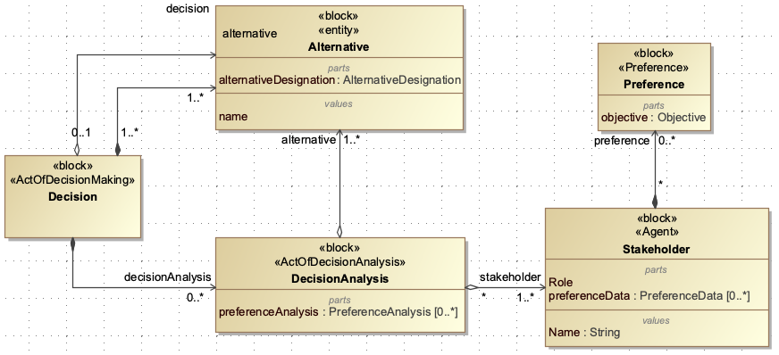
Introduction
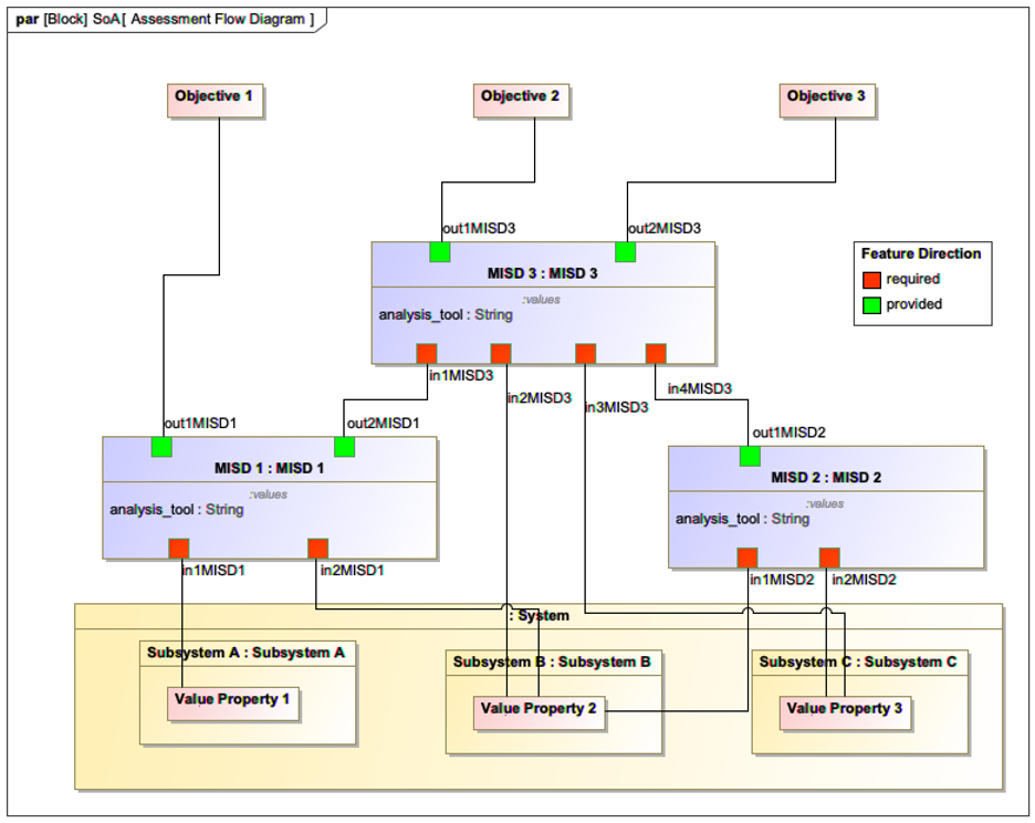
MISD (Model Interface Specification Diagram) is a specialized diagram used to define how data is exchanged between different engineering tools and models in a digital engineering workflow. It specifies which parameters are shared and how they’re formatted, enabling seamless data flow across diverse engineering domains.
Overview
The Model Interface Specification Diagram (MISD) is a critical component of the Digital Engineering Framework for Integration and Interoperability (DEFII). It serves as a formal specification for data interfaces between different engineering tools and models, enabling seamless data exchange within a digital engineering workflow.
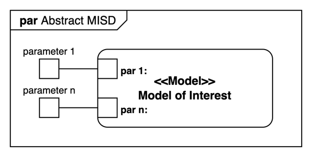
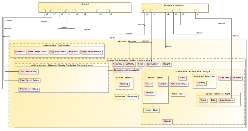
MISD is used in the DEFII framework to specify an interface using the Specified Model Interface (SMI) pattern. It packages individual parameters associated with a system under analysis or design and exposes them to external tools. The MISD is typically implemented using SysML parametric diagrams, which allows it to be integrated directly into the system model.
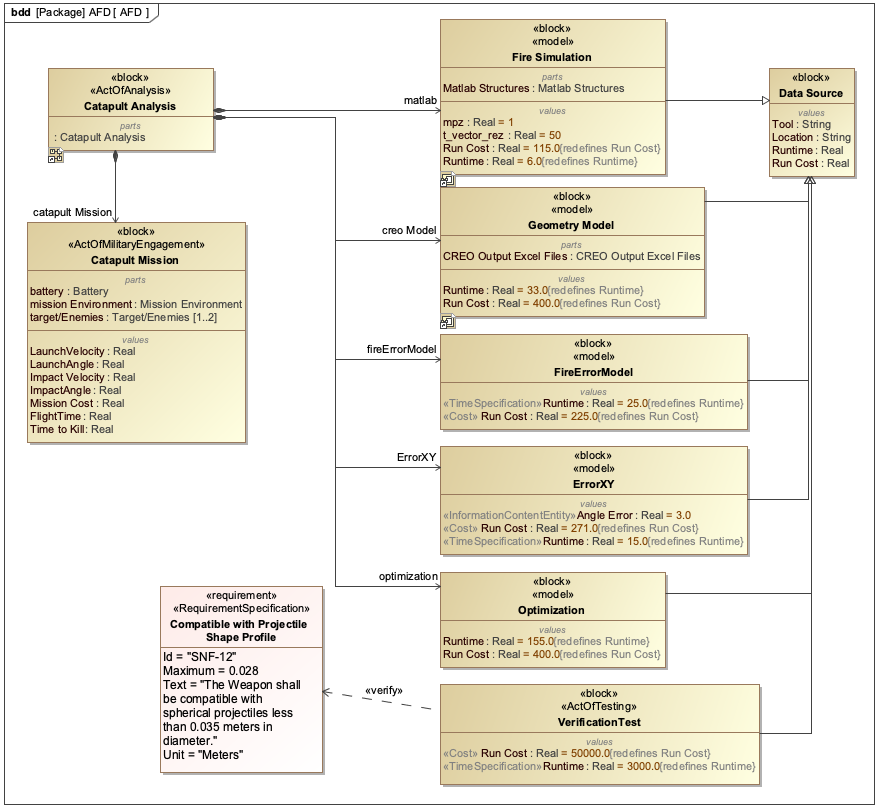
MISD is closely related to the Assessment Flow Diagram (AFD), which defines the overall analysis workflow. While the AFD describes the sequence of analyses and data flow, the MISD specifically defines the data interfaces required for that workflow.
| The MISD is not just a diagram but a formal specification that enables tool-agnostic data exchange. It allows external tools to read and write to the ontology-aligned data without being fully aware of the ontologies at the root of the Authoritative Source of Truth (AST). |
Position in Knowledge Hierarchy
Broader concepts: - SoA (is-a)
Details
The MISD is a key enabler for interoperability in digital engineering environments. Here are the key technical details:
Structure and Implementation
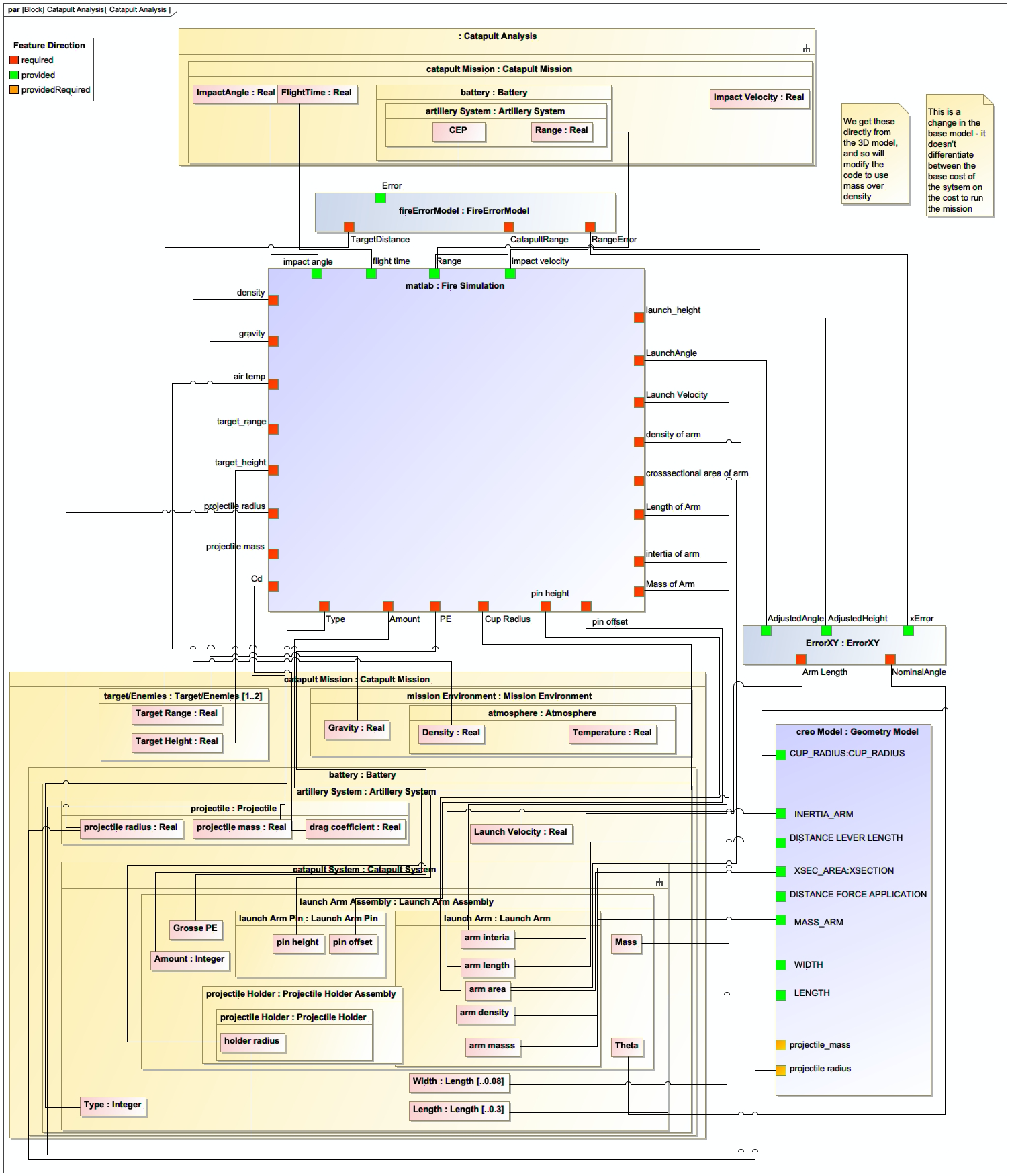
The MISD is implemented as a SysML parametric diagram that specifies: - Input and output parameters for each analysis - Data types and formats - Units of measurement - Constraints and relationships between parameters
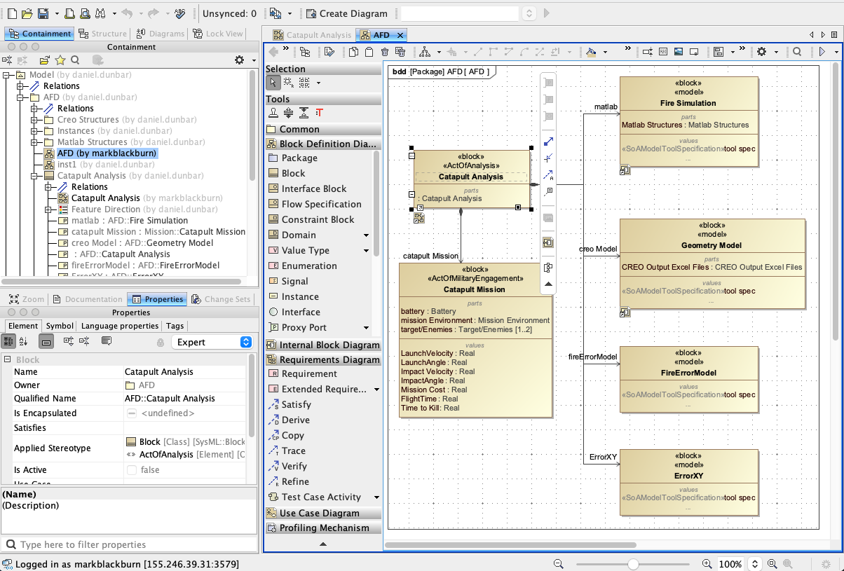
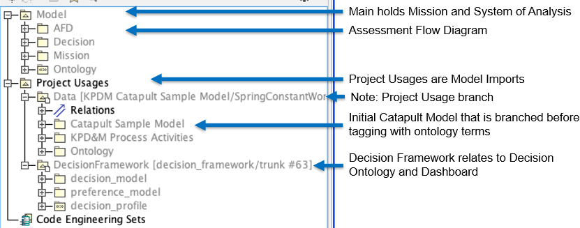
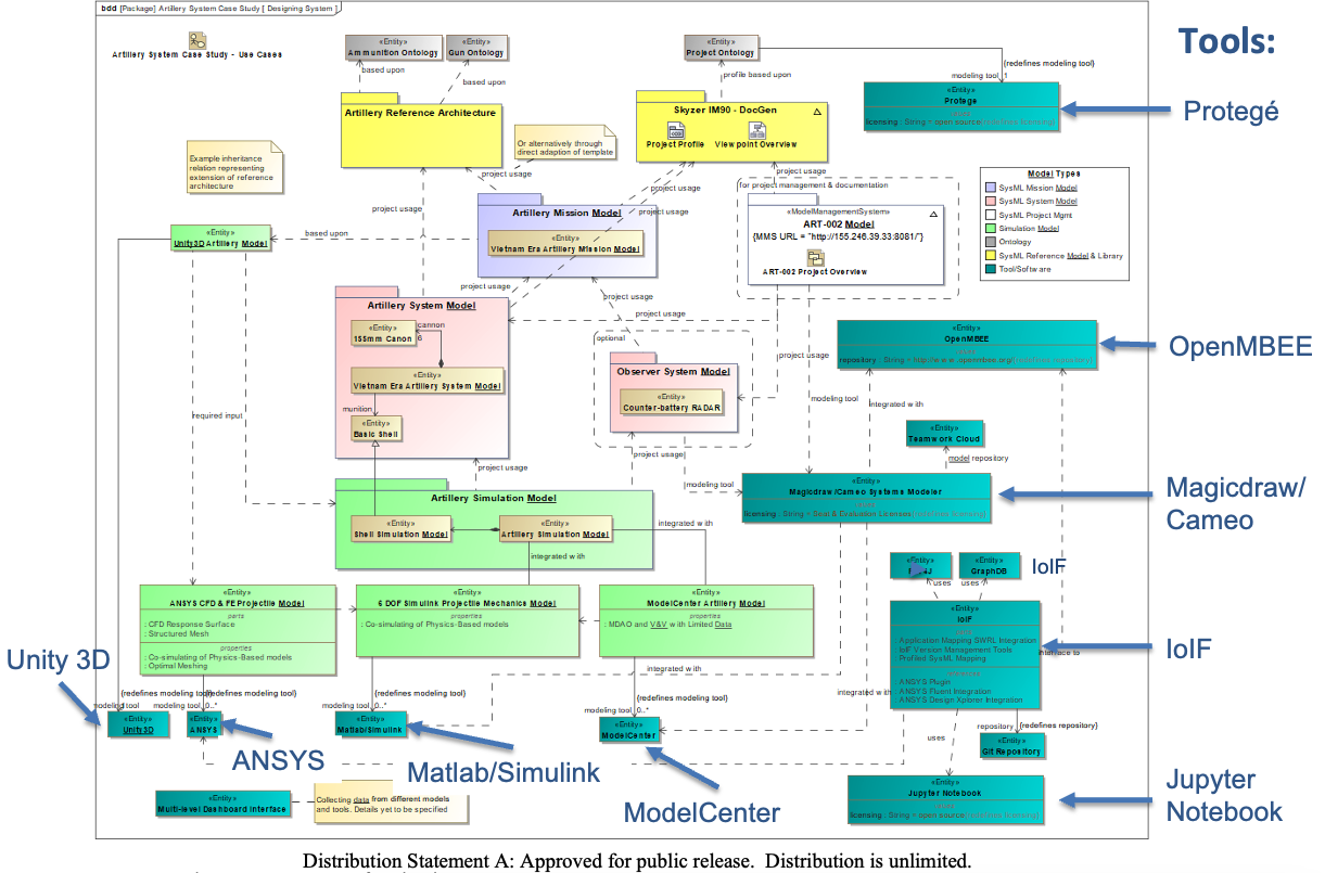
The MISD is "comingled with the system model of the system under design or analysis" as shown in Figure 66 of the context. This integration allows the MISD to be part of the overall system model rather than a separate artifact.
| The MISD must be defined before the analysis workflow can be automated. It provides the necessary specifications for the tool proxies to correctly exchange data between different engineering tools. |
Relationship to Other Concepts
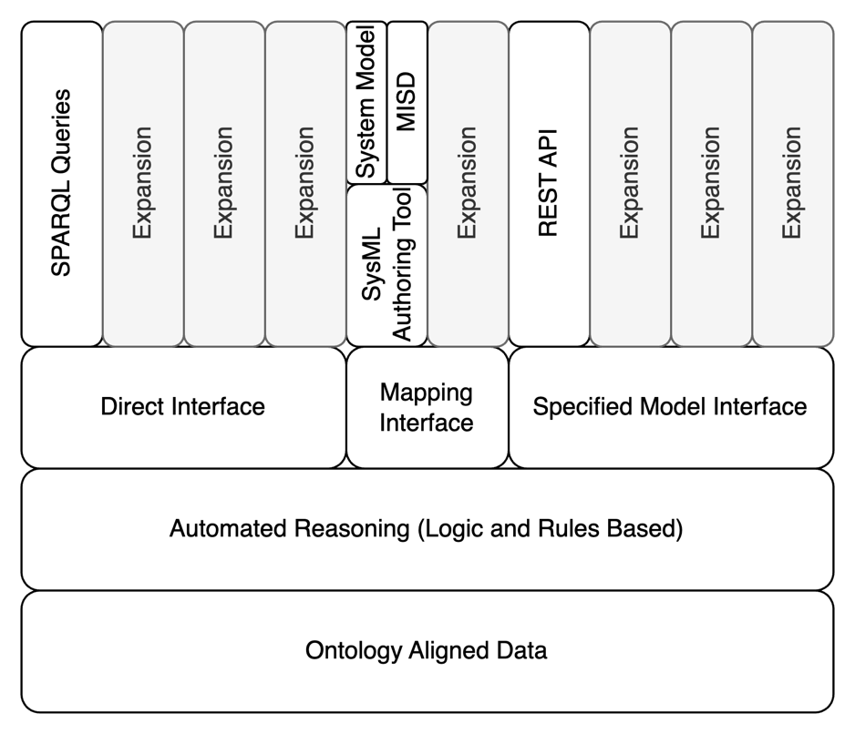
MISD is one of three interface types defined in the DEFII framework:
Interface Type |
Description |
Direct Interface |
Direct invocation of the SWT stack (e.g., SPARQL queries) |
Mapping Interface |
Tool-dependent mapping from tool to ontology |
Specified Model Interface |
Tool-independent access to ontology-aligned data |
MISD specifically falls under the Specified Model Interface category. It is the primary mechanism for exposing parameters from the system model to external tools.
MISD is closely related to the AFD (Assessment Flow Diagram), which defines the overall analysis workflow. The AFD specifies the sequence of analyses, while the MISD specifies the data interfaces required for each analysis. As stated in the context, "The MISD is what is used in the DEFII framework to specify an interface using the Specified Model Interface. It uses the SysML parametric diagram representing the AFD to package individual parameters associated with the system under analysis or design and exposes them to external tools."
Technical Implementation
The MISD is implemented using SysML parametric diagrams with specific stereotypes that map to ontology classes. Key implementation details include:
-
Value properties representing parameters
-
Constraints defining relationships between parameters
-
Stereotypes that map to ontology classes (e.g., [parameter])
-
Integration with the system model through project usages
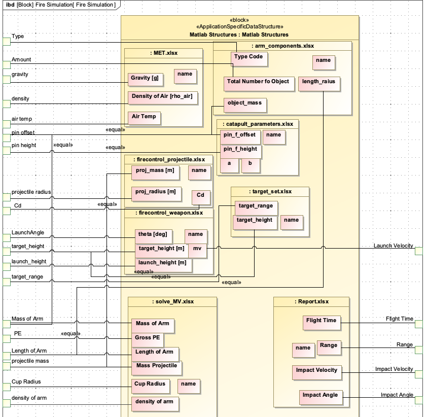
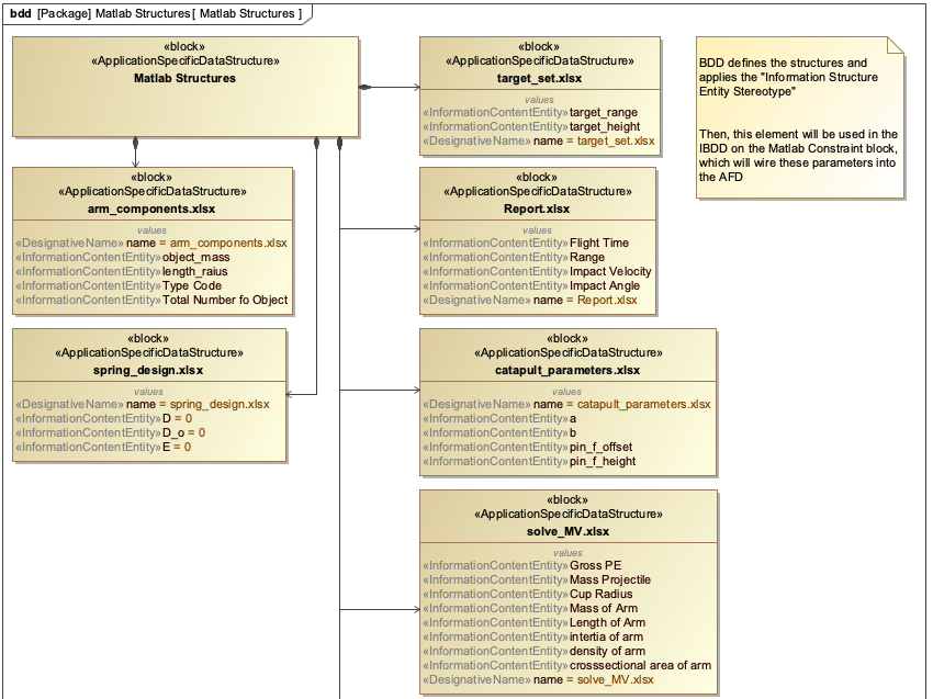
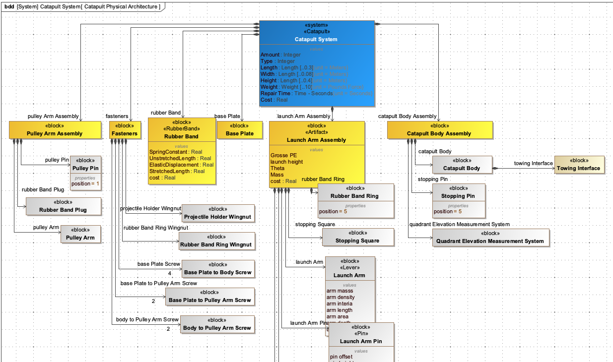
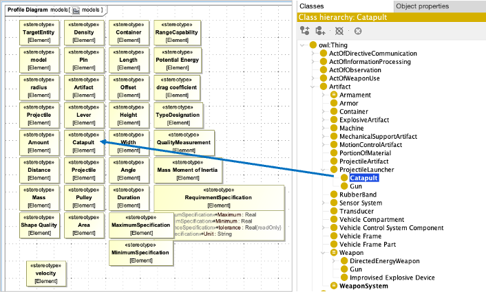
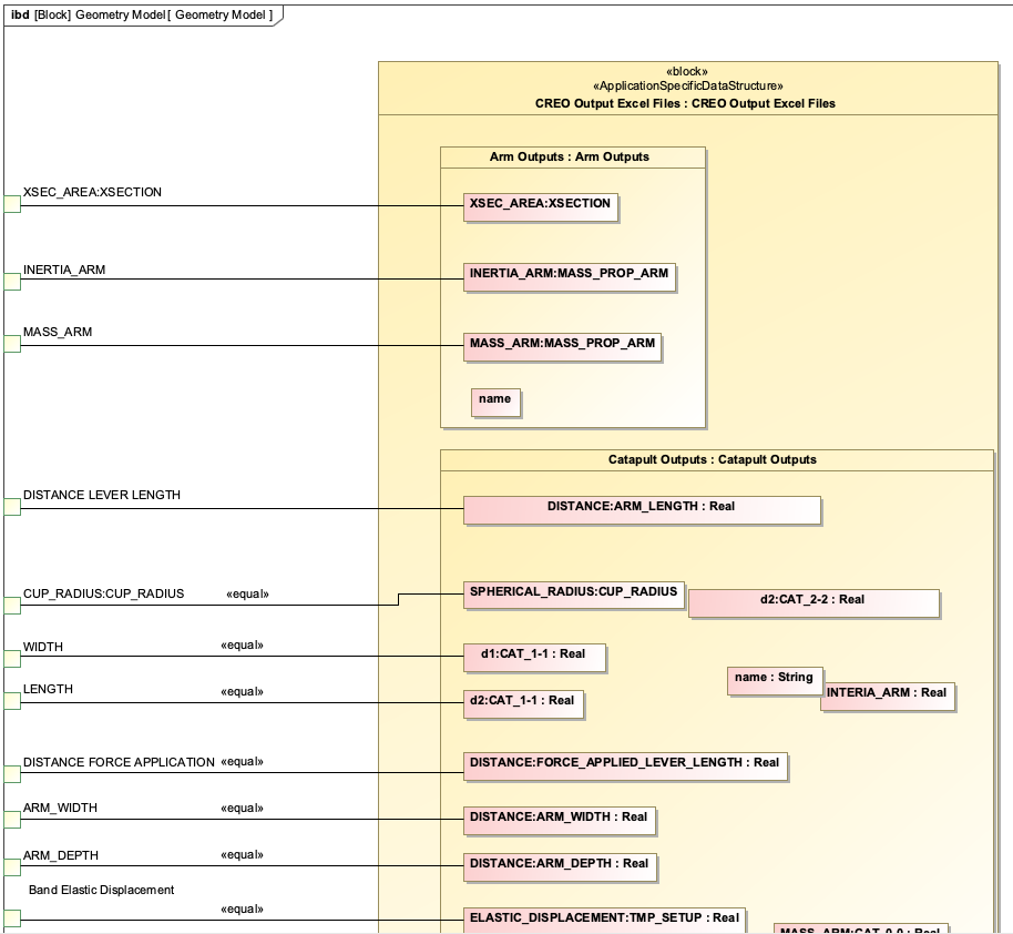
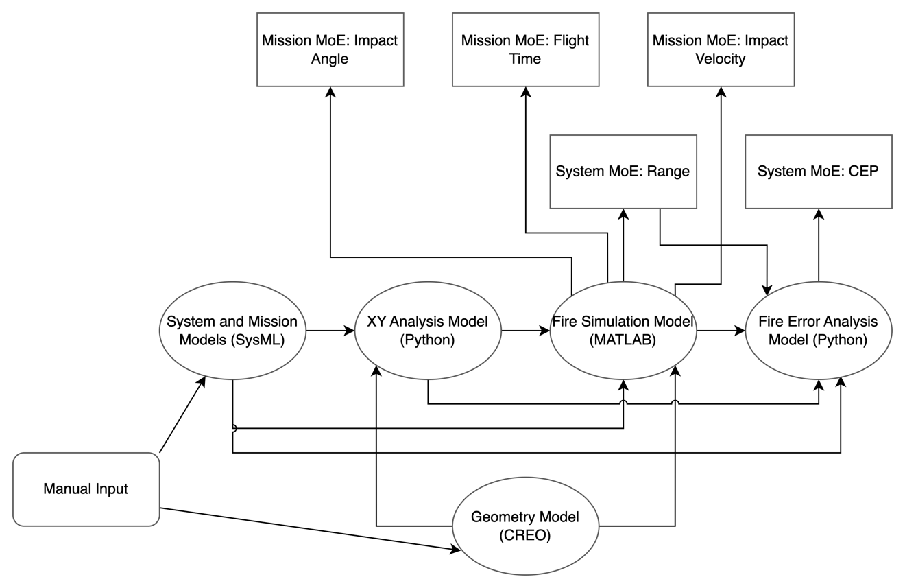
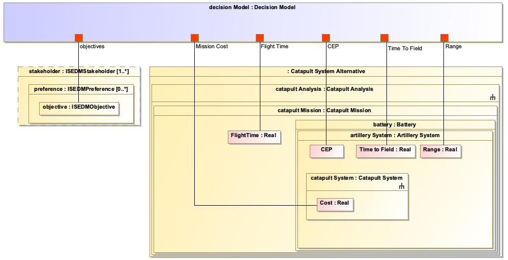
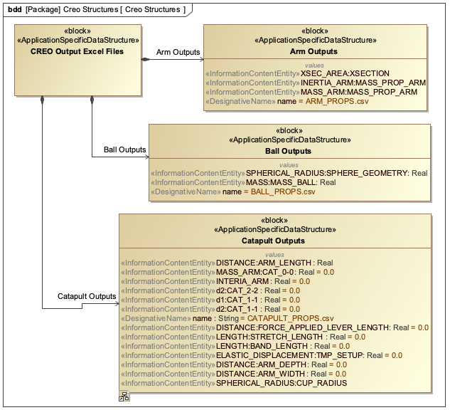
The MISD is typically configured to work with various data formats including CSV, JSON, and REST APIs. For example, in the Catapult use case, the MISD specifies CSV for geometry model inputs and JSON for simulation results.
| When creating MISDs, it’s important to use clear and descriptive names for parameters to ensure readability and maintainability. This is particularly important for large, complex systems where multiple stakeholders may need to understand the interface specifications. |
Practical applications and examples
The Catapult use case demonstrates the practical application of MISD in a real-world digital engineering workflow.
Catapult Case Study
In the Catapult case study, the MISD is used to define the interface for the ballistic simulation analysis. The MISD specifies:
-
Input parameters: projectile mass, launch angle, initial velocity
-
Output parameters: impact angle, flight time, impact velocity, range
-
Data formats: CSV for geometry model, JSON for simulation results
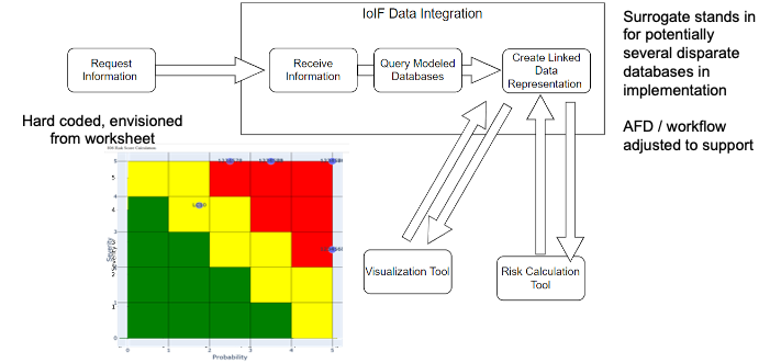
The MISD is integrated into the Catapult system model using SysML, with stereotypes mapping to ontology classes. This allows the IoIF (Armaments Interoperability and Integration Framework) to automatically exchange data between the Catapult system model and the ballistic simulation tool.
| The Catapult MISD is shown in Figure 31 of the context, which is a SysML parametric diagram that serves as a blueprint for facilitating data exchanges between analysis tools. This MISD is configured to work with the AFD (Assessment Flow Diagram) to coordinate the ballistic simulation workflow. |
Workflow Integration
The MISD enables the following workflow steps:
-
IoIF loads the SysML model containing the AFD and MISD
-
IoIF requests interface information for system or mission ontology aligned data using the MISD
-
Tool proxies pull in data from external tools (e.g., using REST GET)
-
Simulations run on the data
-
Results are pushed back to the triplestore using the MISD specifications
-
Results are visualized in dashboards (Decision Dashboard, Digital Thread Impact Analysis)
| When creating MISDs, start with the parameters needed for the highest-level analysis objectives. Then work backward to identify the intermediate parameters required for each analysis step. This approach ensures that the MISD is aligned with the overall analysis goals. |
Related wiki pages
References
Knowledge Graph
Visualize the relationships between MISD and related concepts
Associated Diagrams