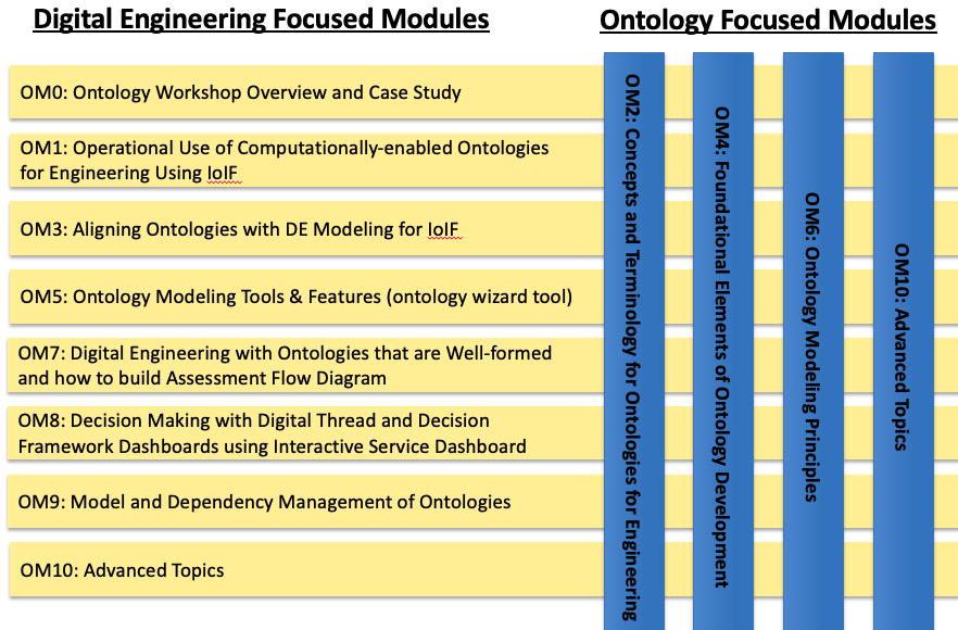
Introduction
Part II explains how to use ontologies in real engineering projects to make different tools and models talk to each other, making it easier to analyze complex systems and make better decisions. It’s like having a universal translator for engineering data.
| This section shows how to operationalize ontologies in digital engineering workflows, moving beyond theory to practical implementation. |
Overview
Part II details the operational implementation of ontologies in digital engineering through the Armaments Interoperability and Integration Framework (IoIF). It covers:
-
How to configure IoIF for specific engineering applications
-
The role of SysML models in ontology alignment
-
Assessment Flow Diagram (AFD) as a workflow specification
-
Tool proxy interfaces for integrating engineering tools
-
Practical workflows for multi-domain analysis
The section demonstrates how ontologies can be used to create interoperable engineering data that supports mission, system, and discipline-specific analysis without requiring deep ontology expertise from most users.
| IoIF hides the complexity of ontologies from typical users by using familiar modeling tools like SysML to configure the ontology-aligned data. |
Position in Knowledge Hierarchy
Broader concepts: - Handbook on Digital Engineering with Ontologies (contains)
Narrower concepts: - SysML (is-a) - IoIF (is-a) - Ontology Alignment (is-a)
Details
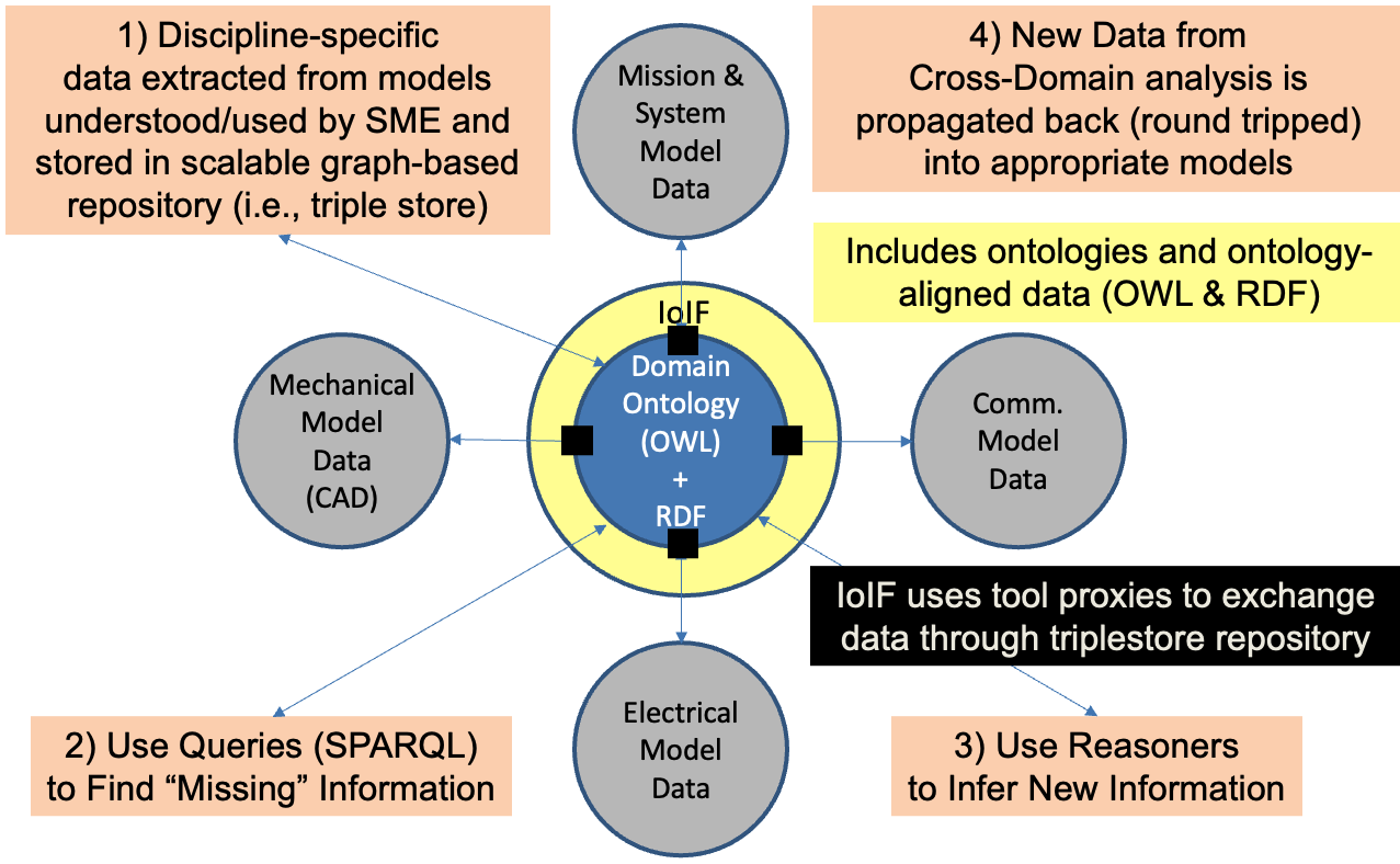
The IoIF Framework
IoIF (Armaments Interoperability and Integration Framework) is a practical implementation of the Digital Engineering Framework for Integration and Interoperability (DEFII). It provides a structured approach to integrating engineering models across domains using ontologies.
IoIF consists of three main components: - Ontology-aligned data: Data structured according to ontologies like BFO (Basic Formal Ontology) - Automated reasoning: Using ontologies to infer new knowledge and ensure consistency - Tool proxy interfaces: Mechanisms for connecting engineering tools to the ontology-aligned data
| IoIF is not an ontology itself, but a framework that uses ontologies to enable interoperability between engineering tools and models. |
Ontology Alignment with SysML
The key to IoIF’s operational success is aligning SysML models with ontologies. This alignment allows engineers to use familiar SysML tools while benefiting from the semantic richness of ontologies.
The alignment process involves: 1. Creating a SysML model with the Mission and System of Analysis (MSoA) 2. Adding an Assessment Flow Diagram (AFD) to specify the workflow 3. Using stereotypes to tag model elements with ontology classes 4. Configuring IoIF to use the AFD for data exchange
|
Use clear, descriptive names for your SysML blocks, properties, and OWL classes to ensure readability and maintainability. For example, use "SafetyMechanism" instead of "SM" or "Safety". |
| Refer back to the principles of ontology alignment discussed in section 5 of the handbook to guide your modeling decisions. |
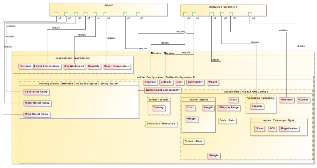
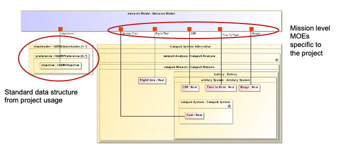
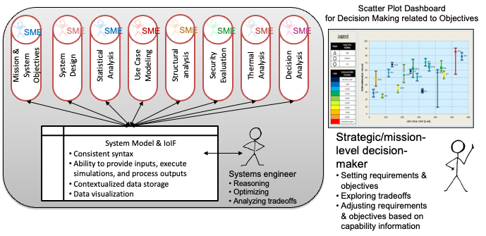
Assessment Flow Diagram (AFD)
The AFD is a SysML parametric diagram that specifies the workflow for analysis. It shows how data flows between different models and simulations.
An AFD typically includes: - System under analysis: The core system being evaluated - Intermediate analysis models: Tools and simulations that process data - High-level objectives: Mission and system-level goals
| The AFD serves as the "blueprint" for the IoIF workflow, specifying which data is needed, where it comes from, and where it goes. |
Element Type |
Description |
Analysis Block |
A SysML element that sits "above" all elements of interest |
Act of Analysis |
A stereotype indicating the type of analysis being performed |
Act of Characterization |
A stereotype indicating data sources or interfaces |
Model |
A stereotype indicating specific engineering models |
IoIF Interface |
A stereotype indicating interfaces to the IoIF framework |
Tool Proxy Interfaces
IoIF uses three types of tool proxy interfaces to connect engineering tools to the ontology-aligned data:
Interface Type |
Description |
Direct Interface |
Direct invocation of the Semantic Web Technology stack (e.g., SPARQL queries) |
Mapping Interface |
Mapping tool-specific data to ontology-aligned data |
Specified Model Interface |
Tool-independent access to ontology-aligned data (e.g., CSV, JSON) |
|
For engineering tools without APIs, file-based interfaces (like CSV) can serve as a temporary solution while developing more robust tool proxies. |
| Data Store(s) are persistent, not generally overwritten, and serve data across tools and analyses. Files are not considered Data Stores but rather interfaces for exchanging data. |
Practical applications and examples
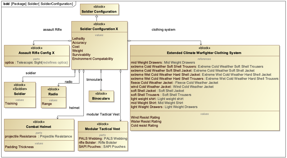
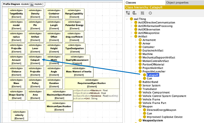
Catapult Use Case
The Catapult use case demonstrates how IoIF operationalizes ontology alignment for engineering analysis. The workflow involves:
-
Creating a SysML model with an AFD
-
Tagging model elements with ontology classes using stereotypes
-
Configuring IoIF to use the AFD for data exchange
-
Running simulations (e.g., geometry, ballistics)
-
Visualizing results in dashboards
| The Catapult model includes four variants (Analysis as Designed, Analysis as Manufactured, Analysis Configuration Changed, Analysis Requirement Changed) to demonstrate different trade space analyses. |
IoIF Workflow Steps
The following steps outline a typical IoIF workflow for a Catapult analysis:
| This workflow uses a Jupyter Notebook to coordinate the analysis, but could also be implemented as a Python script. |
= Initialize IoIF with SysML model
from ioif import IoIF
ioif = IoIF()
ioif.load_sysml_model("catapult_model.psm")

= Set analysis variant
ioif.set_analysis_type("Analysis as Designed")

= Pull data from TWC (Teamwork Cloud)
ioif.pull_data_from_twc()

= Run geometry simulation
ioif.run_simulation("geometry_simulation.py")

= Run ballistic simulation
ioif.run_simulation("ballistic_simulation.m")

= Push results to triplestore
ioif.push_results_to_triplestore()

= Visualize results in Decision Dashboard
ioif.visualize_results("decision_dashboard")| The workflow uses the AFD to determine which data to pull, which simulations to run, and where to push results. |
Workflow Configuration with AFD
The AFD specifies the data flow between models. For the Catapult example, the AFD includes:
-
Input: Geometry data (from Creo)
-
Processing: Ballistic simulation (in MATLAB)
-
Output: Performance metrics (for Decision Dashboard)
| The AFD is a SysML parametric diagram that specifies the data flow between models, making it easy to understand and verify the analysis workflow. |
Related wiki pages
References
Knowledge Graph
Visualize the relationships between Part II concepts
Associated Diagrams