Introduction
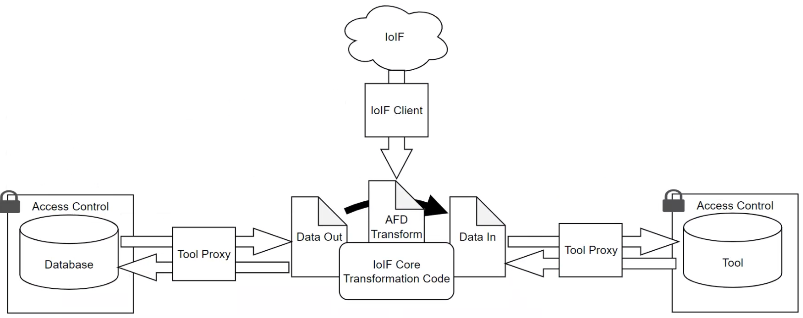
A Model Interface is the connection point between engineering tools and the Armaments Interoperability and Integration Framework (IoIF), enabling seamless data exchange for digital engineering workflows. It serves as the bridge that allows different modeling and simulation tools to interact with ontology-aligned data repositories.
|
Model Interfaces are the "glue" that connects domain-specific engineering tools with the semantic data layer, allowing for interoperability without requiring each tool to understand the underlying ontology structure. |
Overview
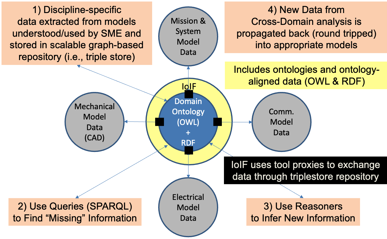
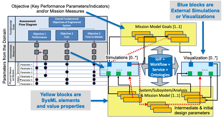
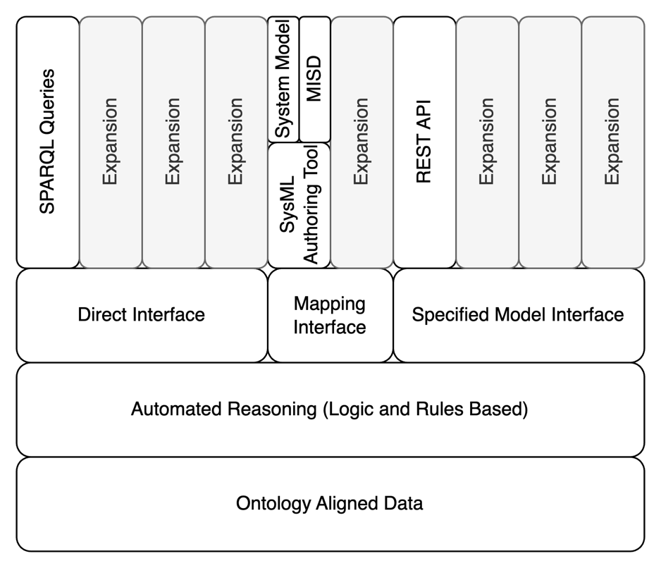
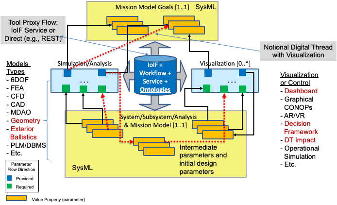
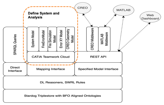
The Model Interface is a critical component of the Digital Engineering Framework for Integration and Interoperability (DEFII), which provides a structured approach for integrating diverse modeling and simulation tools within a digital engineering ecosystem. The DEFII framework uses three distinct types of Model Interfaces to facilitate data exchange between tools and the ontology-aligned data repository:
Interface Type |
Primary Purpose |
Specified Model Interface |
Tool-independent access to ontology-aligned data via standard formats (CSV, JSON) |
Mapping Interface |
Tool-dependent mapping from tool-specific data to ontology-aligned data |
Direct Interface |
Direct invocation of Semantic Web Technology stack (e.g., SPARQL queries) |
These interfaces are designed to support different integration scenarios, from simple direct data access to complex tool-specific mappings, while maintaining the integrity of the ontology-aligned data.
|
The Model Interface concept is foundational to IoIF’s ability to integrate diverse engineering tools into a cohesive digital engineering workflow, enabling cross-domain analysis and visualization without requiring each tool to be explicitly modified for interoperability. |
Position in Knowledge Hierarchy
Broader concepts: - DEFII (is-a)
Narrower concepts: - Specified Model Interface (is-a) - Mapping Interface (is-a) - Direct Interface (is-a)
Details
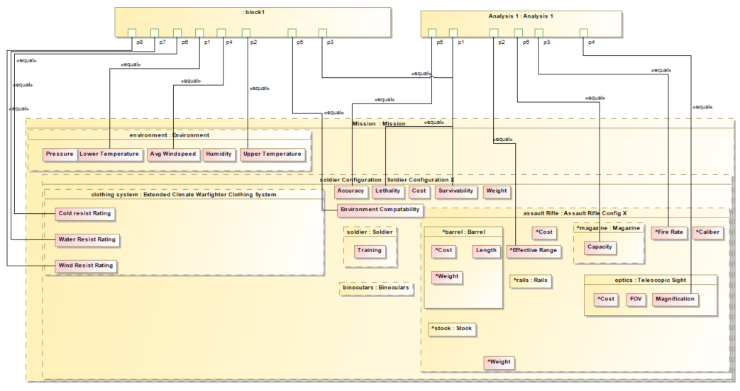
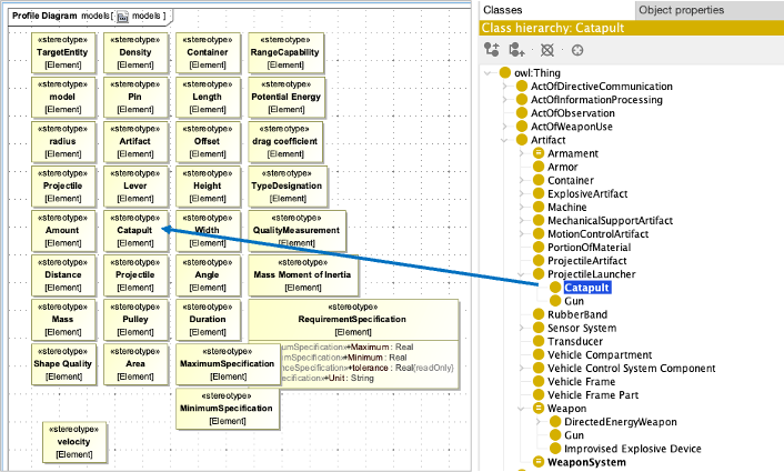
Specified Model Interface
The Specified Model Interface (SMI) is designed to provide tool-independent access to ontology-aligned data. It packages elements from the ontology-aligned data and presents them in standard formats such as CSV or JSON, allowing external tools to read and write data without needing to understand the underlying ontology.
-
How it works:
-
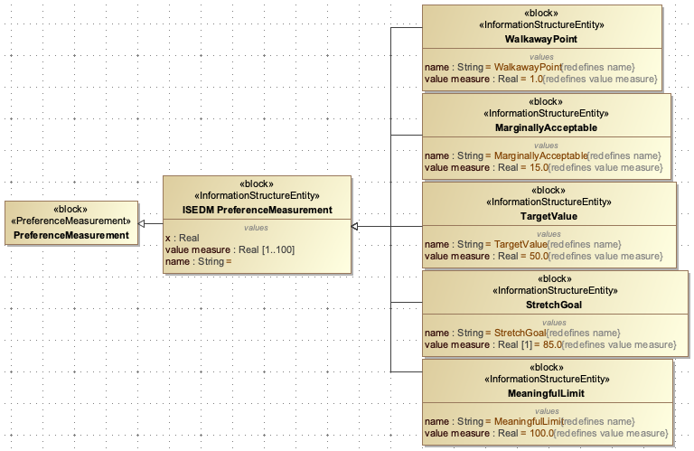
The SMI uses a Model Interface Specification Diagram (MISD) to define the interface structure
-
The MISD is created using SysML parametric diagrams that represent the parameters and data flow
-
Data is retrieved using REST GET requests and returned in standard JSON format
-
The returned data structure includes an "id" field that specifies the root text string for navigating the data
-
-
Key characteristics:
-
Starts with the ontology-aligned data and works outward
-
Enables tool-agnostic access to the ontology data
-
Uses standard data formats (CSV, JSON) for easy integration
-
Supports the IoIF workflow for trade space analysis
-
|
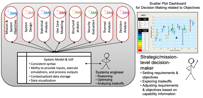
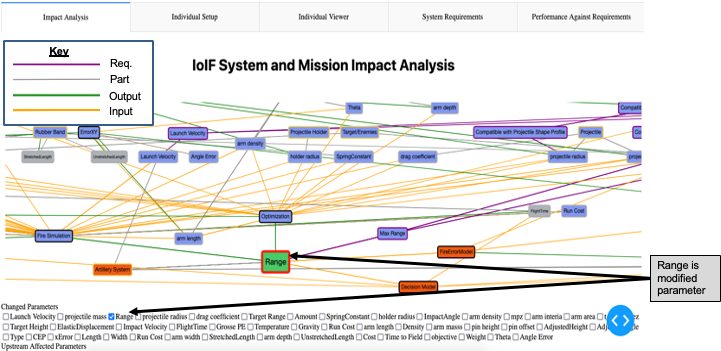
The SMI is particularly valuable for visualization tools like the Decision Dashboard and Digital Thread Impact Analysis, which can consume the standardized data format without needing to understand the ontology structure. |
Mapping Interface
The Mapping Interface (MI) is designed to translate tool-specific data structures into ontology-aligned data. It starts with the tool or model in question and maps relevant portions of that representation to ontology-aligned graph versions of the data.
-
How it works:
-
Uses custom SysML stereotypes in a SysML model to align system models to ontology classes
-
Translates tool-specific data to the ontology structure
-
Typically implemented as a custom tool proxy for each engineering tool
-
May use metadata (in SysML v2) or stereotypes (in SysML v1) for alignment
-
-
Key characteristics:
-
Starts with the tool or model in question and moves toward ontology
-
Requires domain knowledge for mapping rules
-
Fits well with systems engineering context where models contain multiple domain elements
-
Allows for general mapping rules that can be used across multiple domains
-
|
The Mapping Interface is particularly useful when integrating existing engineering tools that don’t natively support ontology alignment, as it provides a bridge between the tool’s data model and the ontology. |
Direct Interface
The Direct Interface (DI) provides direct access to the Semantic Web Technology (SWT) stack, allowing tools to interact with the ontology-aligned data repository directly.
-
How it works:
-
Uses W3C standards like SPARQL query language to search for patterns in the triplestore
-
May use Shapes Constraint Language (SHACL) for closed-world reasoning on ontology-aligned data
-
Allows tools to directly access and manipulate the triplestore
-
Typically used for tools that have direct integration capabilities
-
-
Key characteristics:
-
Uses direct invocation of the SWT technology stack
-
Enables advanced querying and reasoning capabilities
-
May require tool-specific development for integration
-
Supports complex operations like automated reasoning
-
|
The Direct Interface requires a deeper understanding of Semantic Web Technologies and is generally more complex to implement than the other interface types. It’s best suited for tools that already have strong integration capabilities with semantic technologies. |
Practical applications and examples
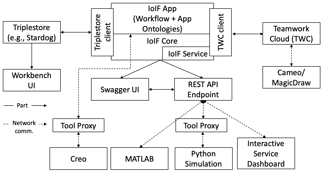
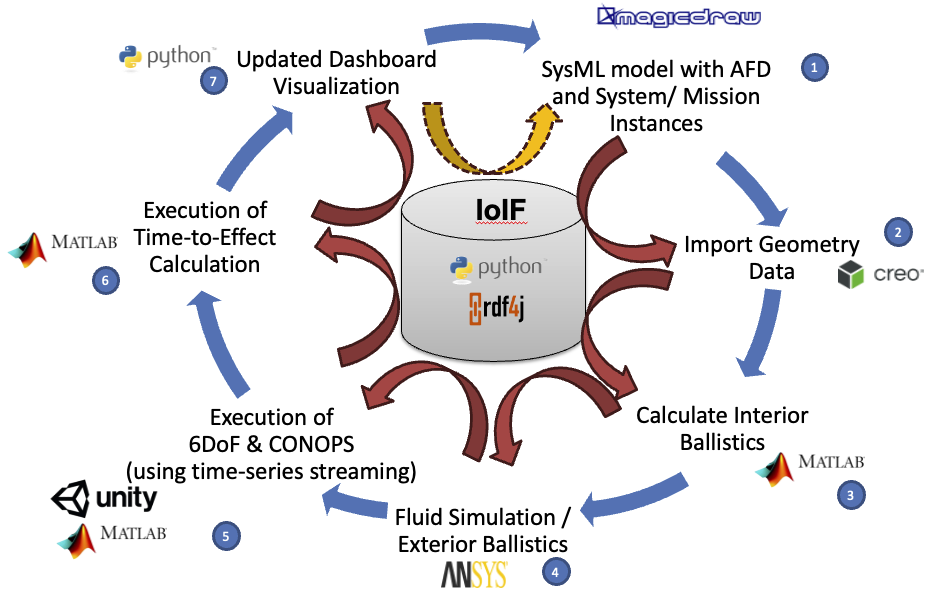
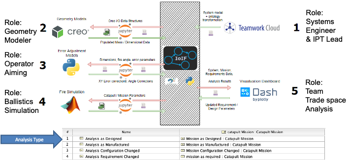
IoIF Workflow with Model Interfaces
The IoIF workflow demonstrates how the three Model Interfaces work together in a practical digital engineering scenario:
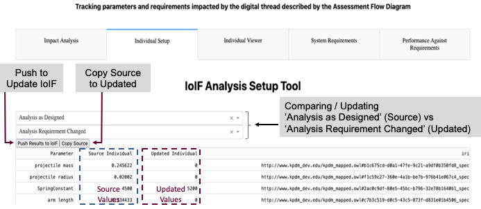
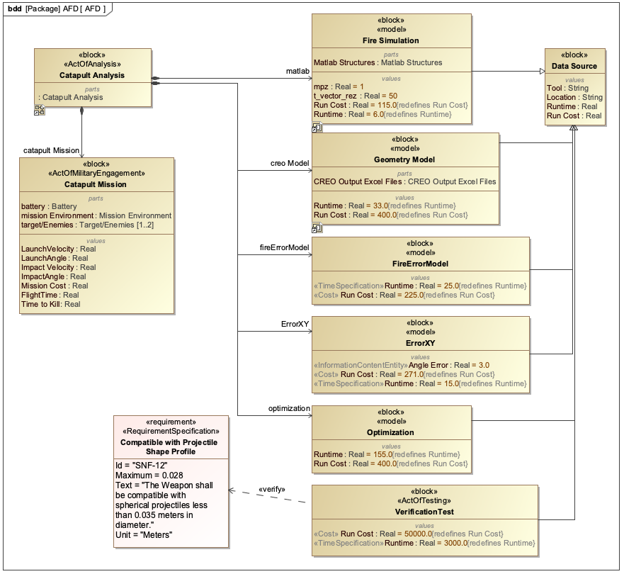
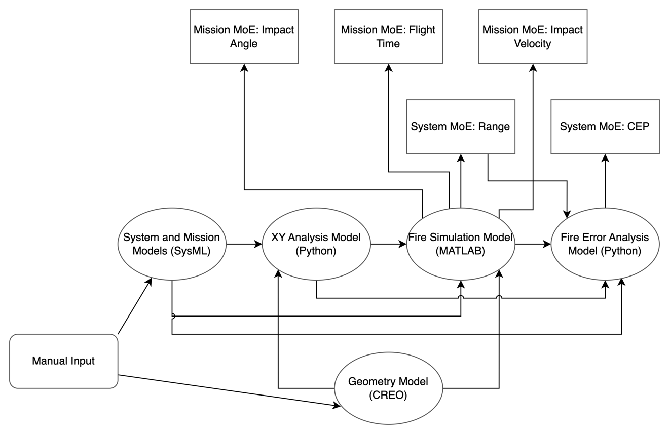
The workflow shown in Figure 9 (Jupyter Notebook IoIF Workflow for Catapult) demonstrates the practical use of Model Interfaces:
-
The workflow initializes with a REST GET from Teamwork Cloud (TWC)
-
The Creo model is pulled into IoIF using a CSV file (Mapping Interface)
-
The simulation of Operator Aiming pulls data from IoIF using REST GET and sends results back using REST PUT
-
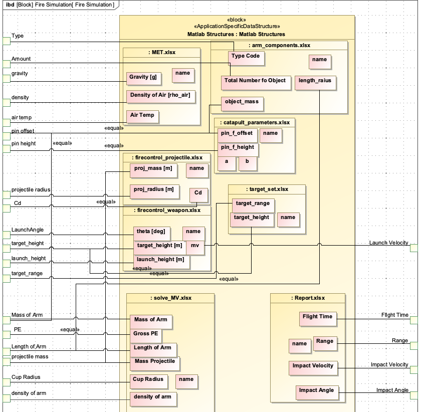
The ballistic simulation (MATLAB) pulls data using webread and sends results using webwrite
-
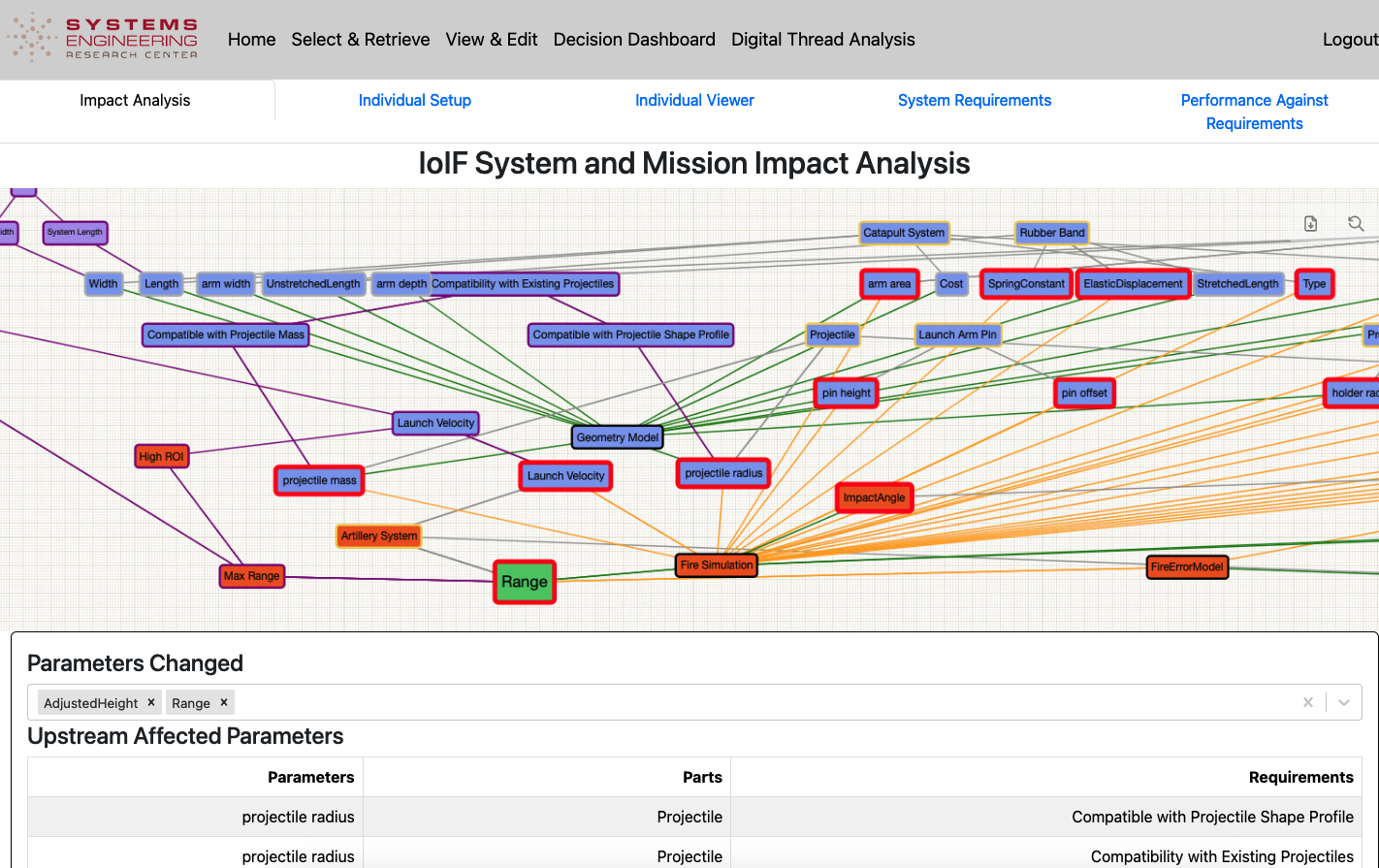
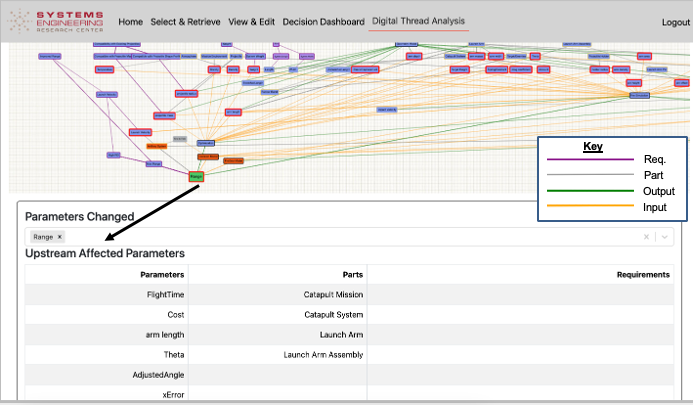
The data in the triplestore is rendered in the Decision Dashboard and Digital Thread Dashboard
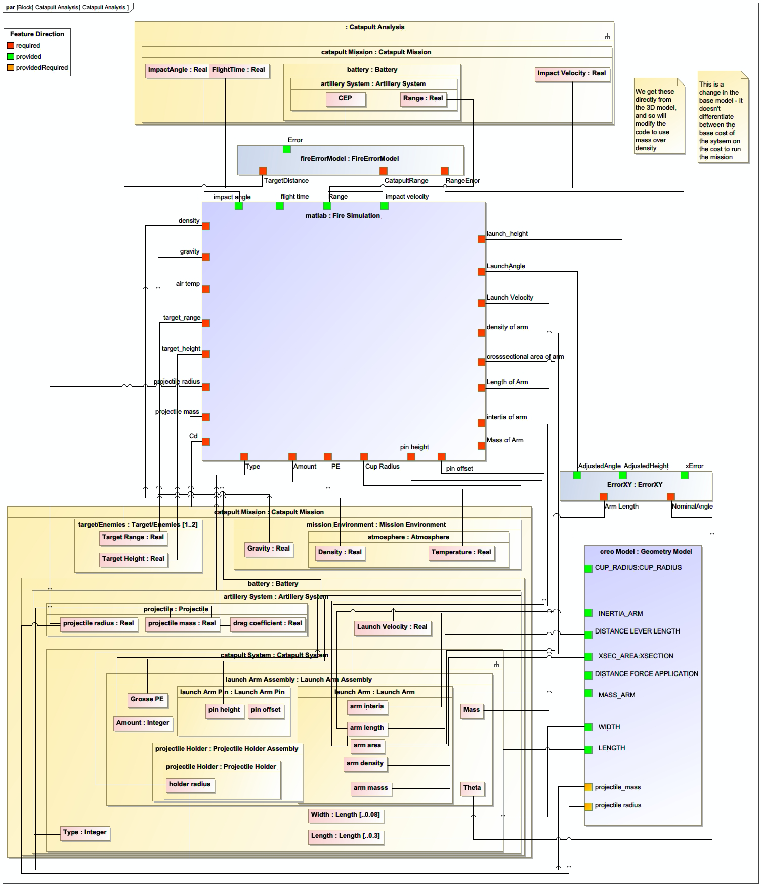
Example: Catapult Use Case
In the Catapult use case, the Model Interfaces are implemented as follows:
Interface Type |
Implementation Details |
Specified Model Interface |
Used for the Decision Dashboard and Digital Thread Impact Analysis dashboards to visualize trade-off data |
Mapping Interface |
Used to translate Creo model data to ontology-aligned data via CSV files |
Direct Interface |
Used for SPARQL queries to the triplestore repository for data retrieval and updates |
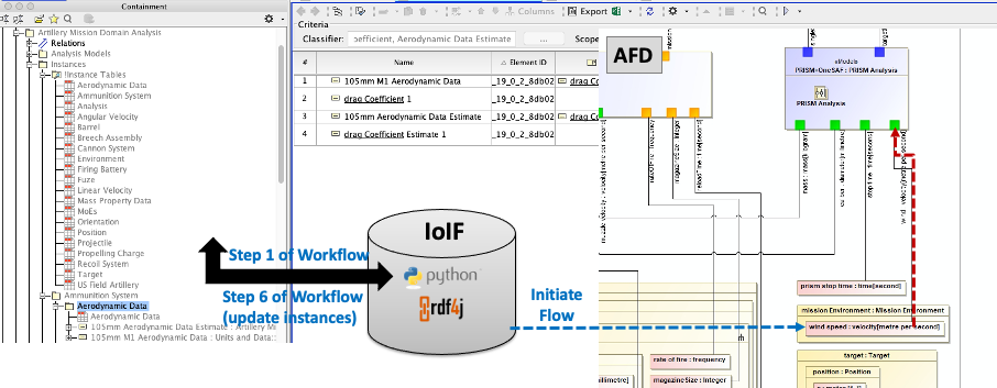
The Catapult example demonstrates how these interfaces work together to enable a cohesive digital engineering workflow:
-
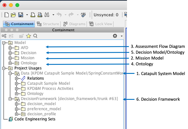
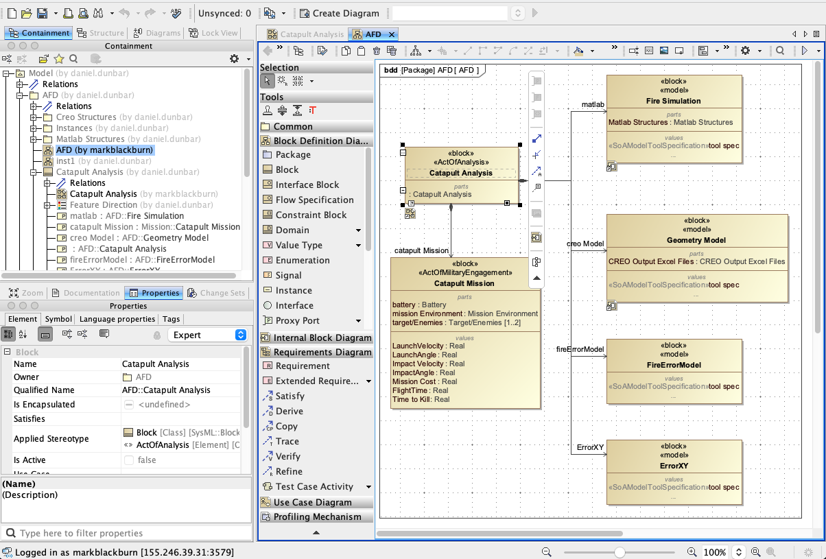
The SysML model with the Assessment Flow Diagram (AFD) configures IoIF
-
The Mapping Interface translates the Creo model data to ontology-aligned format
-
The Direct Interface enables SPARQL queries to access and update the triplestore
-
The Specified Model Interface packages the data for the Decision Dashboard
|
The Catapult example demonstrates that the Model Interfaces enable a "full stack" of models and simulations to work together, transforming traditional stove-piped analysis into an integrated, model-centric engineering process. |
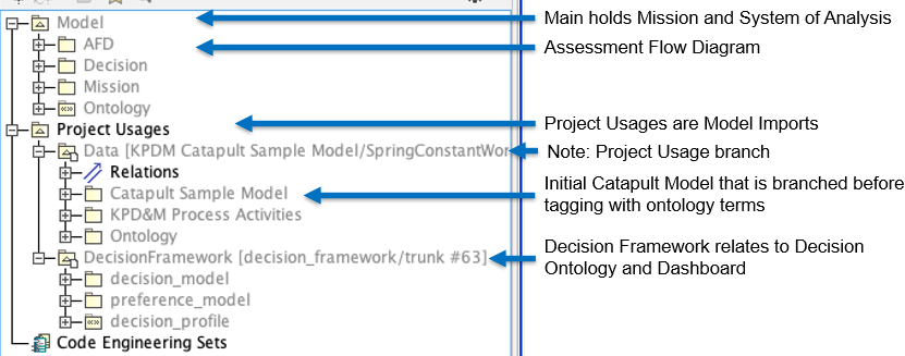
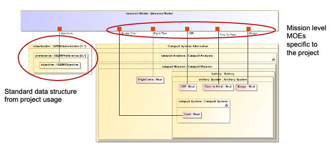
Associated Diagrams