Introduction
The Mapping Interface translates data from engineering tools into a standardized ontology format, enabling seamless data exchange between different modeling tools.
Overview
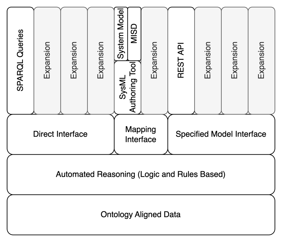
The Mapping Interface is one of three interface types in the Digital Engineering Framework for Integration and Interoperability (DEFII), designed to enable data exchange between engineering tools and ontology-aligned repositories. It functions by taking data from a specific tool or model format and translating it into an ontology-aligned representation that can be stored in a semantic triplestore repository.
The Mapping Interface is particularly valuable in systems engineering contexts where multiple tools with different data structures need to communicate. Unlike the Direct Interface (which uses direct queries to the ontology repository) or the Specified Model Interface (which starts with ontology-aligned data and works outward), the Mapping Interface begins with the tool’s native data structure and maps it to the ontology.
| The Mapping Interface enables interoperability without requiring tool vendors to modify their software, as it handles the translation between the tool’s data format and the ontology-aligned format. |
Position in Knowledge Hierarchy
Broader concepts: - Model Interface (is-a)
Details
The Mapping Interface works through a process of translation that transforms tool-specific data into an ontology-aligned format. This process involves:
-
Data Extraction: Pulling data from the source tool or model
-
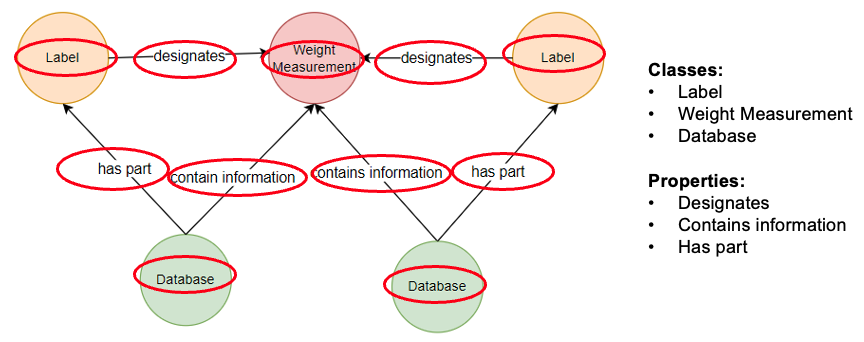
Mapping Definition: Using predefined rules to associate tool-specific data with ontology classes and properties
-
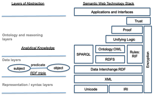
Transformation: Converting the extracted data into RDF triples that align with the ontology
-
Storage: Loading the transformed data into the ontology-aligned repository
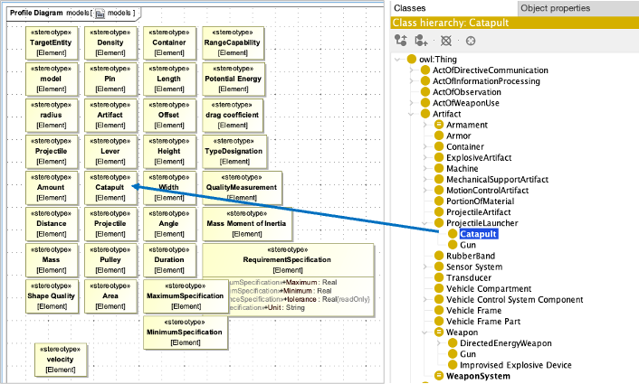
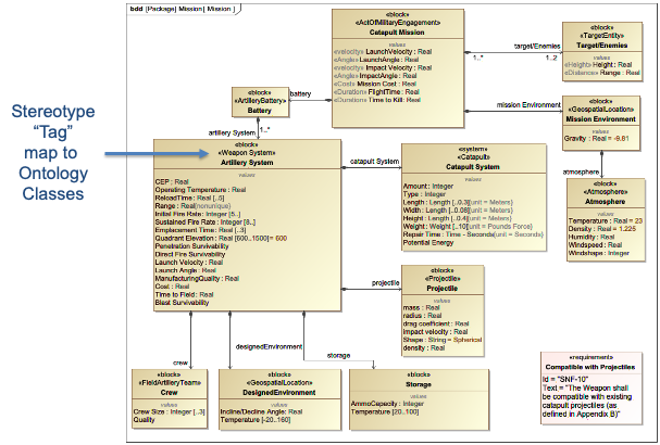
The Mapping Interface is particularly well-suited for use with SysML models in systems engineering, where custom stereotypes can be used to align model elements with ontology classes.
|
When implementing a Mapping Interface, use SysML stereotypes (in SysML v1) or metadata (in SysML v2) to tag model elements with their corresponding ontology classes. This creates a clear, consistent mapping that can be reused across multiple projects. |
Mapping Process Workflow
The Mapping Interface workflow follows these key steps:
Step |
Description |
1. Data Extraction |
Extract data from the source tool or model (e.g., SysML model) |
2. Mapping Configuration |
Apply predefined mapping rules to translate tool-specific data to ontology-aligned format |
3. Transformation |
Convert extracted data into RDF triples using the mapping rules |
4. Storage |
Load the transformed data into the ontology-aligned repository |
5. Verification |
Validate the mapped data against the ontology constraints |
Key Implementation Considerations
The following considerations are critical for successful implementation of a Mapping Interface:
| The Mapping Interface should be designed to be domain-agnostic, allowing the same mapping rules to be applied across multiple domains without requiring specific domain knowledge in the mapping rules themselves. |
| When creating mapping rules, use descriptive names for the ontology classes and properties to ensure readability and maintainability. This is particularly important for collaboration between systems engineers and ontologists. |
| Avoid creating overly complex mappings that require extensive domain knowledge. The goal is to create mappings that can be understood and maintained by systems engineers without requiring deep ontology expertise. |
Practical applications and examples
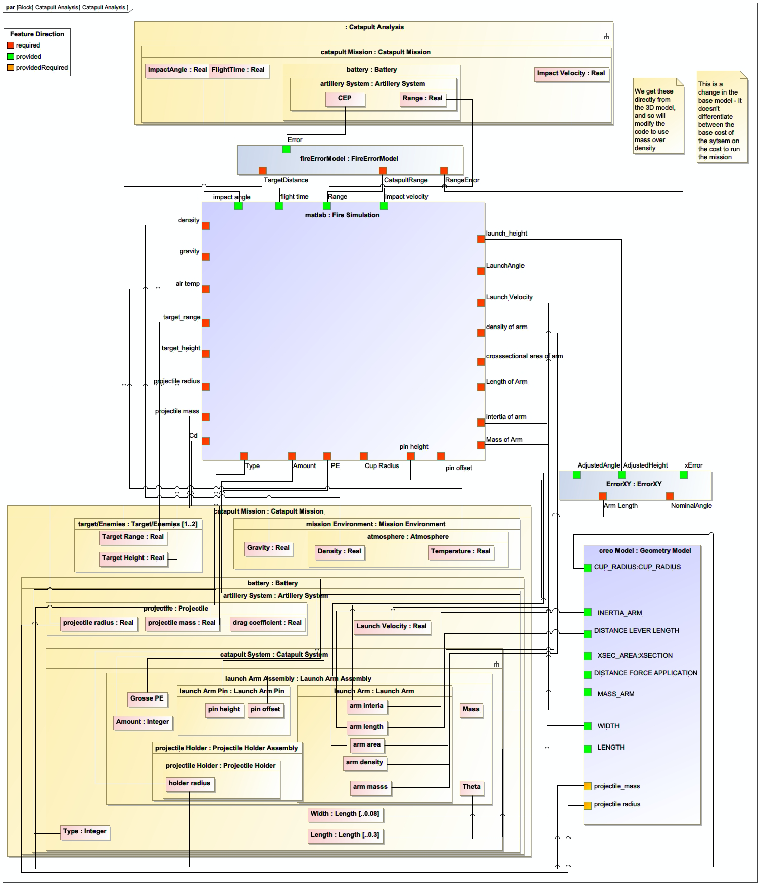
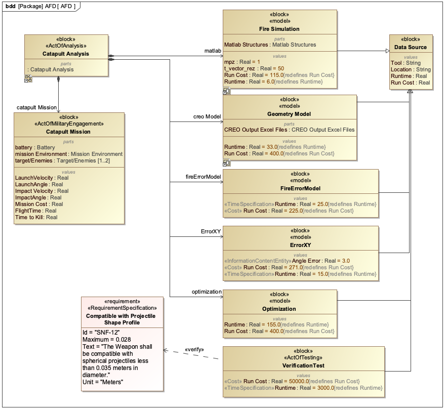
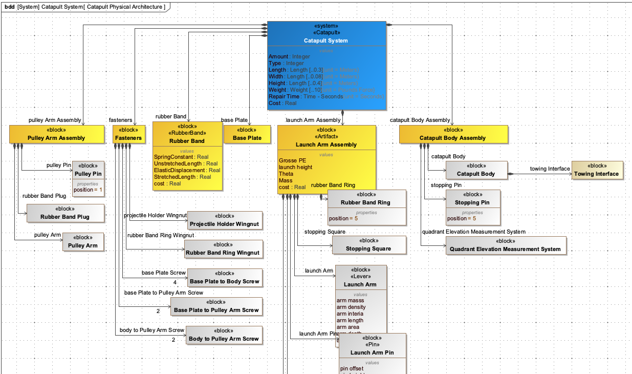
The Catapult use case demonstrates the practical application of the Mapping Interface in systems engineering.
Catapult Case Study
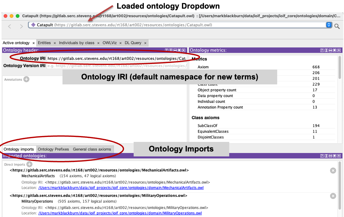
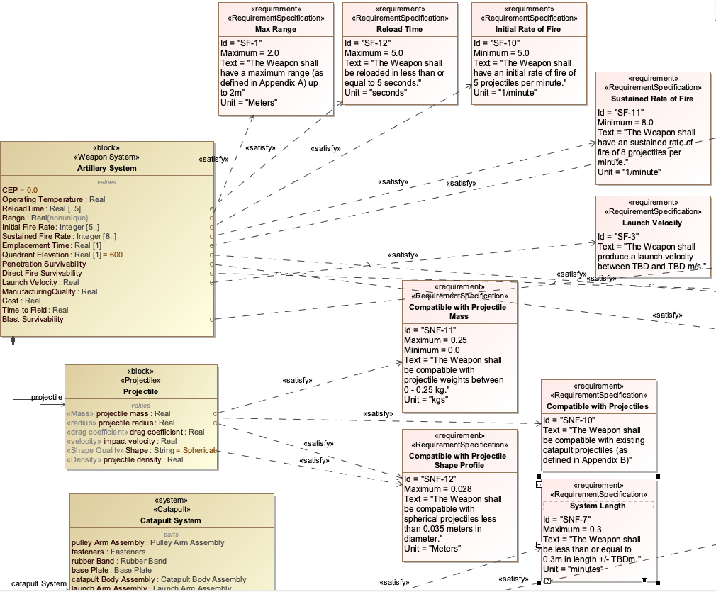
In the Catapult case study, the Mapping Interface is used to align a SysML model of a catapult system with the Catapult ontology. The process involves:
-
SysML Model Creation: A SysML model is created with the catapult system, including blocks for the main components (e.g., arm, base, trigger mechanism)
-
Ontology Alignment: Custom SysML stereotypes are applied to the model elements to map them to corresponding ontology classes
-
Mapping Configuration: A mapping configuration is defined that specifies how the SysML model elements correspond to the ontology
-
Data Transformation: The SysML model is transformed into RDF triples that align with the ontology
-
Repository Loading: The transformed data is loaded into the ontology-aligned repository
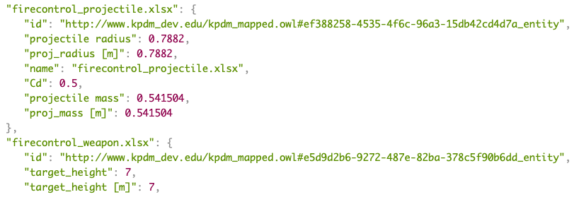
The mapping configuration for the Catapult example uses the following approach:
= Example mapping configuration for Catapult system
mapping_rules = [
    {
        "source": "SysML:Block",
        "target": "CatapultOntology:CatapultComponent",
        "properties": {
            "name": "SysML:Block.name",
            "weight": "SysML:Property.weight",
            "material": "SysML:Property.material"
        }
    },
    {
        "source": "SysML:Connector",
        "target": "CatapultOntology:Connection",
        "properties": {
            "type": "SysML:Connector.type",
            "strength": "SysML:Connector.strength"
        }
    }
]|
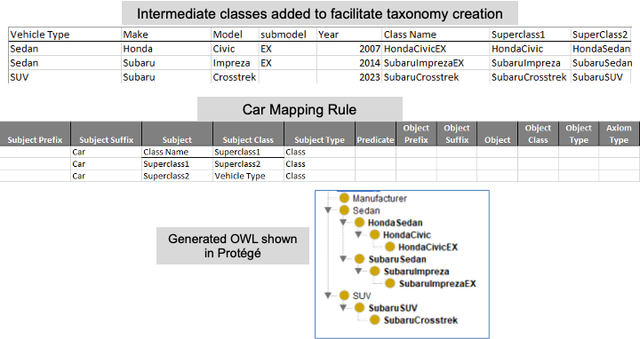
The mapping rules can be stored in a CSV or Excel file and processed using the Ontology Wizard, which is designed to handle mappings from tabular data formats to ontologies. |
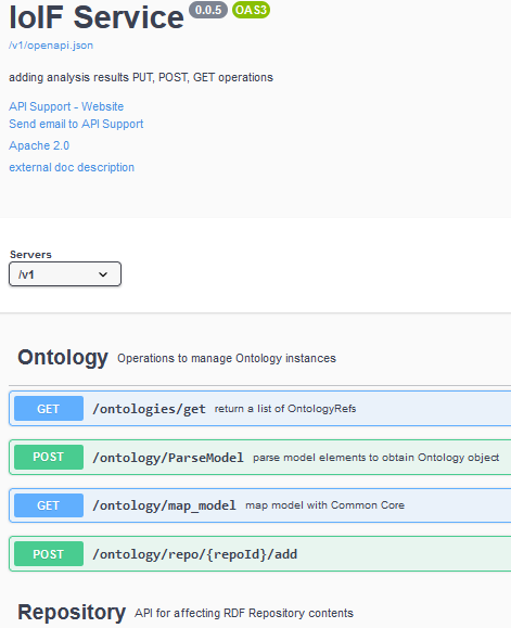
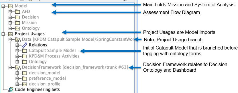
Workflow Integration
The Mapping Interface integrates with the overall IoIF workflow as shown in Figure 9 of the context:
-
The SysML model is pulled from Teamwork Cloud (TWC)
-
The Mapping Interface processes the model, translating it to ontology-aligned format
-
The transformed data is loaded into the triplestore repository
-
The data is used in subsequent analyses (e.g., ballistic simulations)
-
Results from analyses are pushed back to the repository
-
The Decision Dashboard visualizes the results
Associated Diagrams